Lessons learned Past Present and Future in CTF





- Slides: 42
Lessons learned (Past, Present and Future) in CTF 3 Frank Tecker – CERN Motivation CTF 3 Preliminary Phase Present CTF 3 (up to DL) Future CTF 3 (CR and beyond) Conclusion Frank Tecker Lessons Learned (Past, Present and Future) in CTF 3 CLIC-ACE, 21. 6. 2007
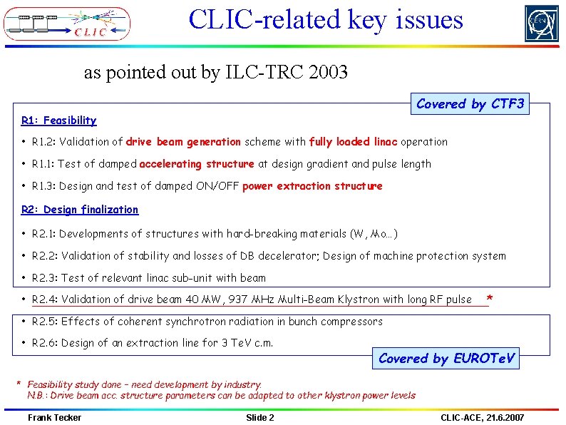
CLIC-related key issues as pointed out by ILC-TRC 2003 Covered by CTF 3 R 1: Feasibility • R 1. 2: Validation of drive beam generation scheme with fully loaded linac operation • R 1. 1: Test of damped accelerating structure at design gradient and pulse length • R 1. 3: Design and test of damped ON/OFF power extraction structure R 2: Design finalization • R 2. 1: Developments of structures with hard-breaking materials (W, Mo…) • R 2. 2: Validation of stability and losses of DB decelerator; Design of machine protection system • R 2. 3: Test of relevant linac sub-unit with beam • R 2. 4: Validation of drive beam 40 MW, 937 MHz Multi-Beam Klystron with long RF pulse * • R 2. 5: Effects of coherent synchrotron radiation in bunch compressors • R 2. 6: Design of an extraction line for 3 Te. V c. m. Covered by EUROTe. V * Feasibility study done – need development by industry. N. B. : Drive beam acc. structure parameters can be adapted to other klystron power levels Frank Tecker Slide 2 CLIC-ACE, 21. 6. 2007
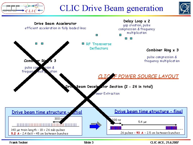
CLIC Drive Beam generation Delay Loop 2 Drive Beam Accelerator gap creation, pulse compression & frequency multiplication efficient acceleration in fully loaded linac RF Transverse Deflectors Combiner Ring 3 pulse compression & frequency multiplication CLIC RF POWER SOURCE LAYOUT Drive Beam Decelerator Section (2 26 in total) Power Extraction Drive beam time structure - final Drive beam time structure - initial 300 ns 140 ms train length - 18 26 sub-pulses 5. 2 A - 2. 4 Ge. V – 45 cm between bunches Frank Tecker 5. 4 ms 26 pulses – 93 A – 2. 5 cm between bunches Slide 3 CLIC-ACE, 21. 6. 2007
CTF 3 demonstrate Drive Beam generation (fully loaded acceleration, bunch frequency multiplication 8 x) Test CLIC accelerating structures Test power production structures (PETS) 30 GHz “PETS Line” Injector Linac Bunch length chicane RF deflector Combiner Ring Delay Loop TL 1 Laser 30 GHz test area CLEX Frank Tecker Slide 4 TL 2 CLIC-ACE, 21. 6. 2007
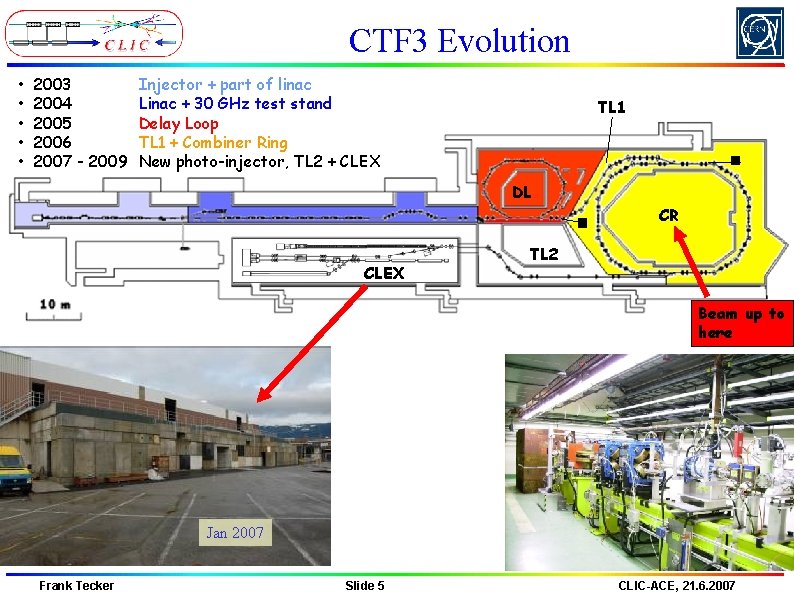
CTF 3 Evolution • • • 2003 2004 2005 2006 2007 - 2009 Injector + part of linac Linac + 30 GHz test stand Delay Loop TL 1 + Combiner Ring New photo-injector, TL 2 + CLEX 2004 TL 1 2005 DL CR CLEX TL 2 Beam up to here Jan 2007 Frank Tecker Slide 5 CLIC-ACE, 21. 6. 2007
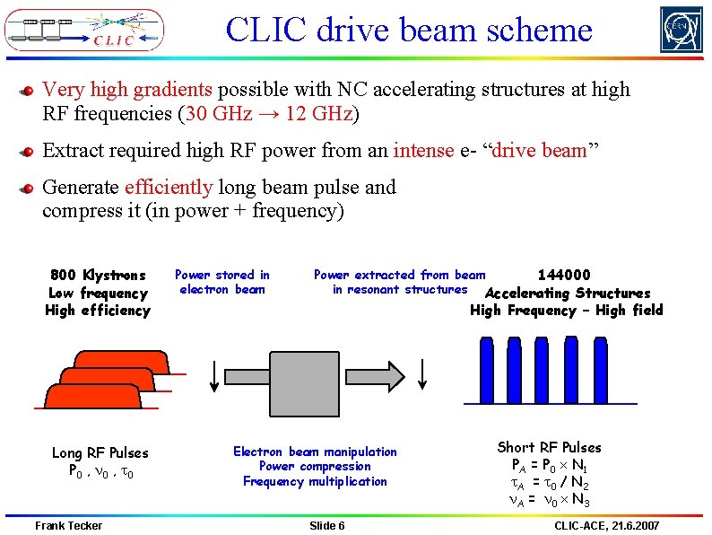
CLIC drive beam scheme Very high gradients possible with NC accelerating structures at high RF frequencies (30 GHz → 12 GHz) Extract required high RF power from an intense e- “drive beam” Generate efficiently long beam pulse and compress it (in power + frequency) 800 Klystrons Low frequency High efficiency Long RF Pulses P 0 , n 0 , t 0 Frank Tecker Power stored in electron beam Power extracted from beam 144000 in resonant structures Accelerating Structures High Frequency – High field Electron beam manipulation Power compression Frequency multiplication Slide 6 Short RF Pulses PA = P 0 N 1 t. A = t 0 / N 2 n. A = n 0 N 3 CLIC-ACE, 21. 6. 2007
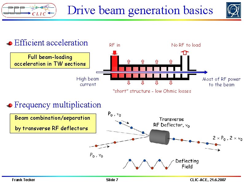
Drive beam generation basics Efficient acceleration RF in No RF to load Full beam-loading acceleration in TW sections High beam current Most of RF power to the beam “short” structure - low Ohmic losses Frequency multiplication Beam combination/separation by transverse RF deflectors Frank Tecker Slide 7 CLIC-ACE, 21. 6. 2007
Demonstration of frequency multiplication Frank Tecker Slide 8 CLIC-ACE, 21. 6. 2007
Combination by RF deflectors in a ring combination factors up to 5 reachable in a ring Frank Tecker Slide 9 CLIC-ACE, 21. 6. 2007
Combination setup Developed a setup procedure to optimize combination 5 parameters Amplitude and phase in each deflector RF frequency (no wiggler for path length tuning) Monitor trajectory differences over various turns Frank Tecker Slide 10 CLIC-ACE, 21. 6. 2007
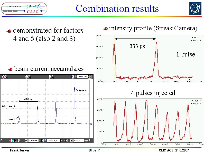
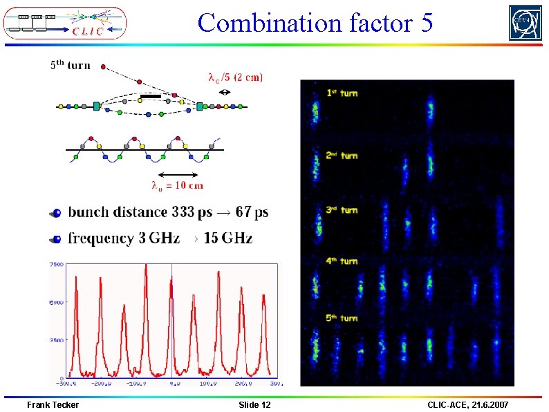
Combination results intensity profile (Streak Camera) demonstrated for factors 4 and 5 (also 2 and 3) 333 ps 1 pulse beam current accumulates 4 pulses injected Frank Tecker Slide 11 CLIC-ACE, 21. 6. 2007
Combination factor 5 Frank Tecker Slide 12 CLIC-ACE, 21. 6. 2007
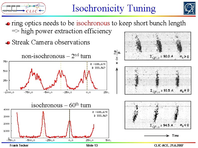
Isochronicity Tuning ring optics needs to be isochronous to keep short bunch length => high power extraction efficiency Streak Camera observations non-isochronous – 2 nd turn isochronous – 60 th turn Frank Tecker Slide 13 CLIC-ACE, 21. 6. 2007
Bunch spacing variations would reduce RF extraction efficiency variations were observed (for large orbit oscillations) theoretically understood, vanish when D=D’=0 no deterioration of the power production Frank Tecker Slide 14 CLIC-ACE, 21. 6. 2007
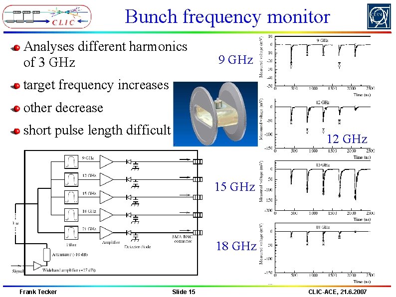
Bunch frequency monitor Analyses different harmonics of 3 GHz 9 GHz target frequency increases other decrease short pulse length difficult 12 GHz 15 GHz 18 GHz Frank Tecker Slide 15 CLIC-ACE, 21. 6. 2007
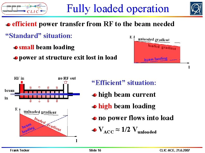
Fully loaded operation efficient power transfer from RF to the beam needed “Standard” situation: small beam loading power at structure exit lost in load “Efficient” situation: high beam current high beam loading no power flows into load VACC ≈ 1/2 Vunloaded Frank Tecker Slide 16 CLIC-ACE, 21. 6. 2007
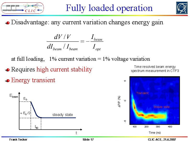
Fully loaded operation Disadvantage: any current variation changes energy gain at full loading, 1% current variation = 1% voltage variation Time resolved beam energy spectrum measurement in CTF 3 Requires high current stability E 0 /2 0 Transient DP/P (%) Ebeam 5 Energy transient Steady state -5 steady state tfill 100 t Frank Tecker 200 300 400 Time (ns) Slide 17 CLIC-ACE, 21. 6. 2007
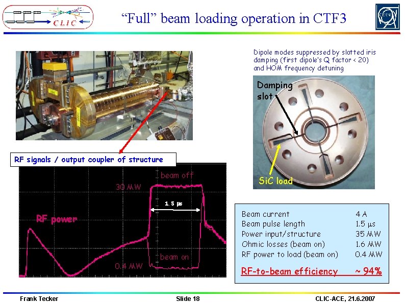
“Full” beam loading operation in CTF 3 Dipole modes suppressed by slotted iris damping (first dipole’s Q factor < 20) and HOM frequency detuning Damping slot RF signals / output coupler of structure beam off 30 MW Si. C load 1. 5 ms RF power 0. 4 MW Frank Tecker beam on Slide 18 Beam current Beam pulse length Power input/structure Ohmic losses (beam on) RF power to load (beam on) 4 A 1. 5 ms 35 MW 1. 6 MW 0. 4 MW RF-to-beam efficiency ~ 94% CLIC-ACE, 21. 6. 2007
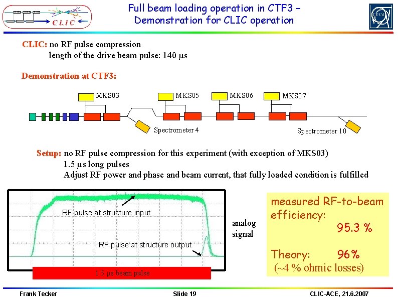
Full beam loading operation in CTF 3 – Demonstration for CLIC operation CLIC: no RF pulse compression length of the drive beam pulse: 140 µs Demonstration at CTF 3: MKS 03 MKS 05 MKS 06 Spectrometer 4 MKS 07 Spectrometer 10 Setup: no RF pulse compression for this experiment (with exception of MKS 03) 1. 5 µs long pulses Adjust RF power and phase and beam current, that fully loaded condition is fulfilled RF pulse at structure input analog signal RF pulse at structure output 1. 5 µs beam pulse Frank Tecker Slide 19 measured RF-to-beam efficiency: 95. 3 % Theory: 96% (~4 % ohmic losses) CLIC-ACE, 21. 6. 2007
30 GHz test line Mid-linac power station Test stand CLEX Two-beam Test Area High-power transfer line Main Beam Injector HIGH POWER RF SOURCES m a e B High-gradient test stand, CTF 2 CTF 3 linac PETS branch Frank Tecker Slide 20 CLIC-ACE, 21. 6. 2007
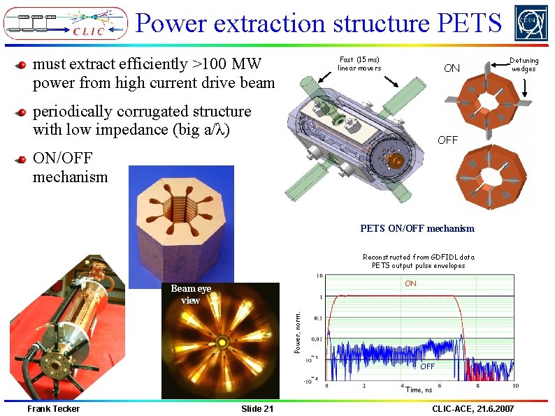
Power extraction structure PETS must extract efficiently >100 MW power from high current drive beam Fast (15 ms) linear movers ON periodically corrugated structure with low impedance (big a/λ) Detuning wedges OFF ON/OFF mechanism PETS ON/OFF mechanism Reconstructed from GDFIDL data PETS output pulse envelopes ON Power, norm. Beam eye view OFF Time, ns Frank Tecker Slide 21 CLIC-ACE, 21. 6. 2007
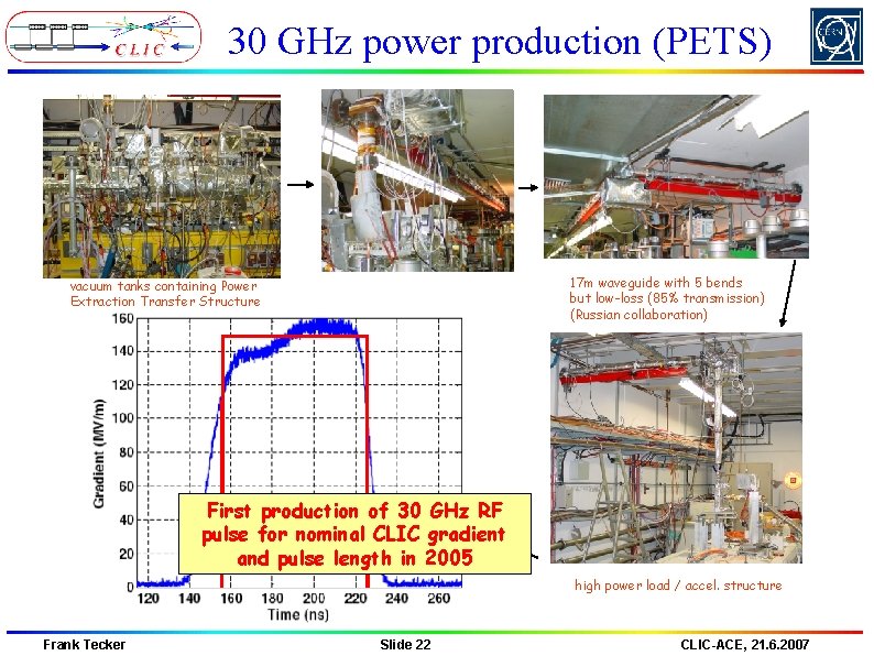
30 GHz power production (PETS) 17 m waveguide with 5 bends but low-loss (85% transmission) (Russian collaboration) vacuum tanks containing Power Extraction Transfer Structure First production of 30 GHz RF pulse for nominal CLIC gradient and pulse length in 2005 high power load / accel. structure Frank Tecker Slide 22 CLIC-ACE, 21. 6. 2007
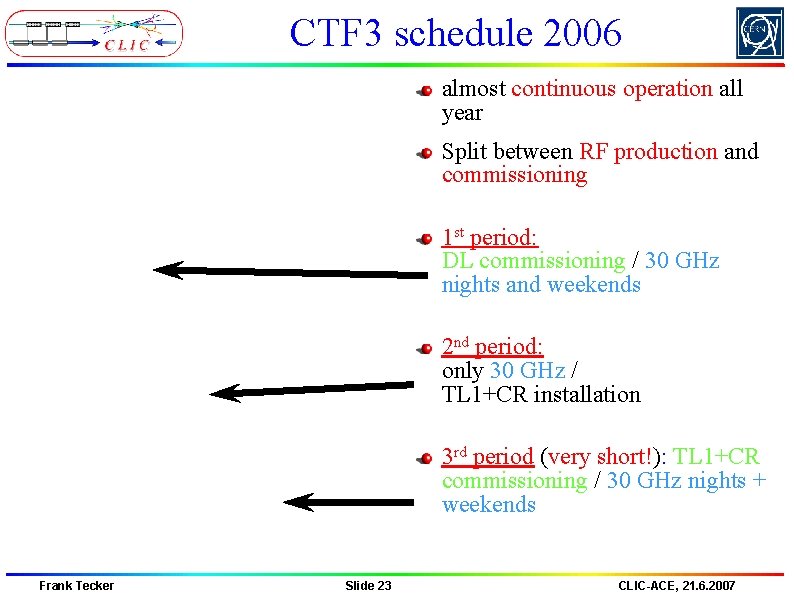
CTF 3 schedule 2006 almost continuous operation all year Split between RF production and commissioning 1 st period: DL commissioning / 30 GHz nights and weekends 2 nd period: only 30 GHz / TL 1+CR installation 3 rd period (very short!): TL 1+CR commissioning / 30 GHz nights + weekends Frank Tecker Slide 23 CLIC-ACE, 21. 6. 2007
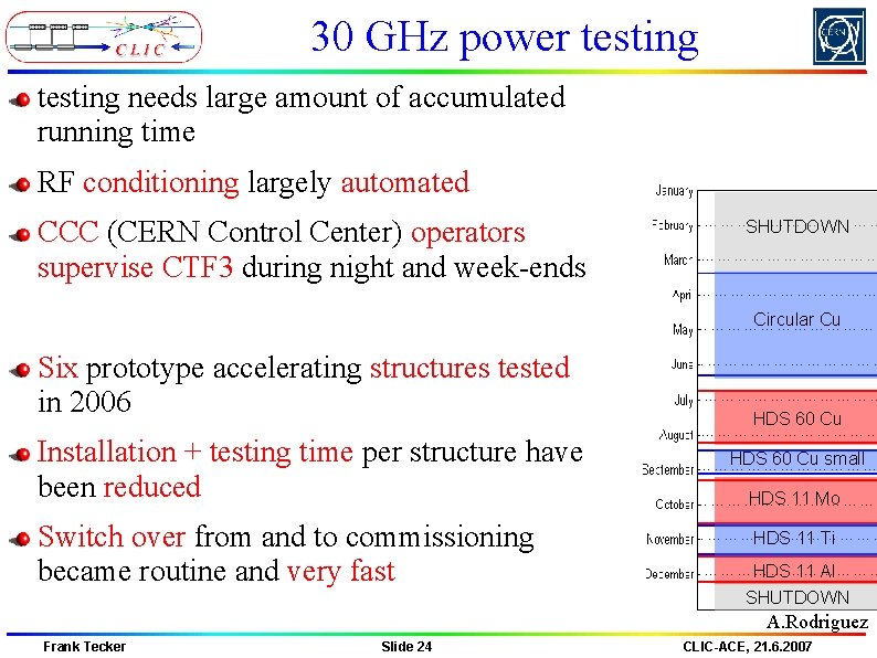
30 GHz power testing needs large amount of accumulated running time RF conditioning largely automated CCC (CERN Control Center) operators supervise CTF 3 during night and week-ends SHUTDOWN Circular Cu Six prototype accelerating structures tested in 2006 Installation + testing time per structure have been reduced Switch over from and to commissioning became routine and very fast HDS 60 Cu small HDS 11 Mo HDS 11 Ti HDS 11 Al SHUTDOWN A. Rodriguez Frank Tecker Slide 24 CLIC-ACE, 21. 6. 2007
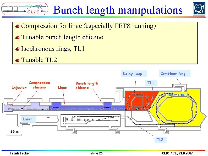
Bunch length manipulations Compression for linac (especially PETS running) Tunable bunch length chicane Isochronous rings, TL 1 Tunable TL 2 Combiner Ring Delay Loop Compression chicane Injector Linac Bunch length chicane TL 1 Laser TL 2 Frank Tecker Slide 25 CLIC-ACE, 21. 6. 2007
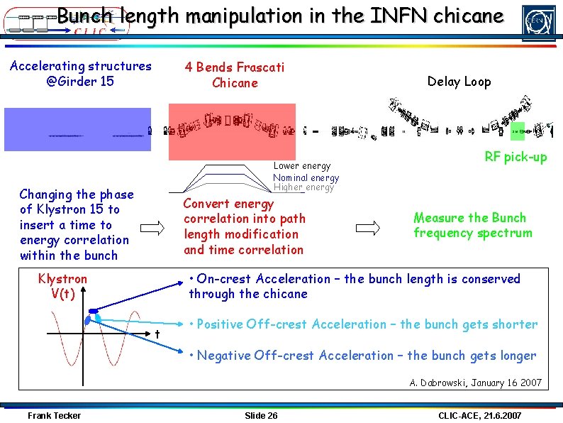
Bunch length manipulation in the INFN chicane Accelerating structures @Girder 15 4 Bends Frascati Chicane Lower energy Nominal energy Higher energy Changing the phase of Klystron 15 to insert a time to energy correlation within the bunch Convert energy correlation into path length modification and time correlation Delay Loop RF pick-up Measure the Bunch frequency spectrum • On-crest Acceleration – the bunch length is conserved through the chicane Klystron V(t) t • Positive Off-crest Acceleration – the bunch gets shorter • Negative Off-crest Acceleration – the bunch gets longer A. Dabrowski, January 16 2007 Frank Tecker Slide 26 CLIC-ACE, 21. 6. 2007
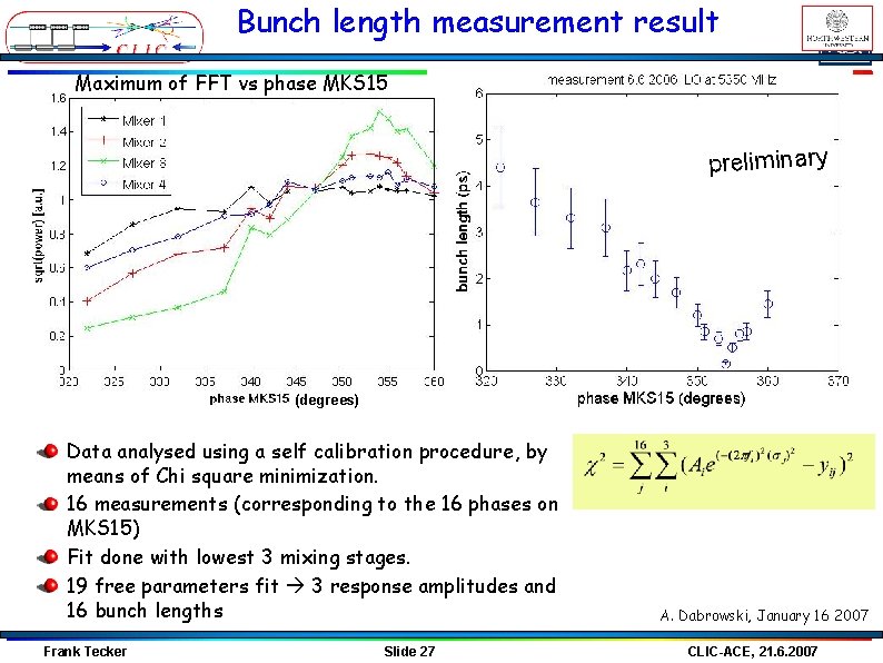
Bunch length measurement result Maximum of FFT vs phase MKS 15 preliminary (degrees) Data analysed using a self calibration procedure, by means of Chi square minimization. 16 measurements (corresponding to the 16 phases on MKS 15) Fit done with lowest 3 mixing stages. 19 free parameters fit 3 response amplitudes and 16 bunch lengths Frank Tecker Slide 27 A. Dabrowski, January 16 2007 CLIC-ACE, 21. 6. 2007
CTF 3 Delay Loop Frank Tecker Slide 28 CLIC-ACE, 21. 6. 2007
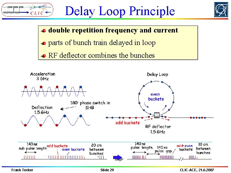
Delay Loop Principle double repetition frequency and current parts of bunch train delayed in loop RF deflector combines the bunches Frank Tecker Slide 29 CLIC-ACE, 21. 6. 2007
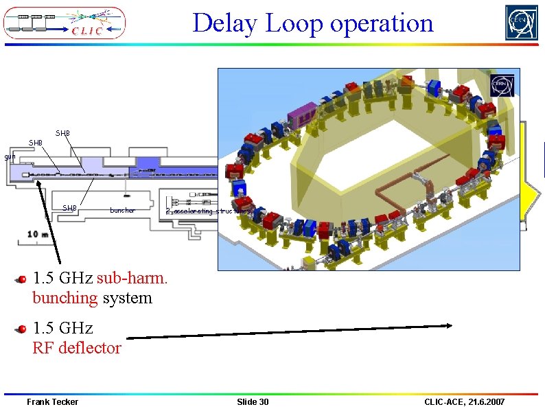
Delay Loop operation TL 1 SHB 2005 SHB 2004 DL gun CR SHB buncher CLEX 2 accelerating structures TL 2 1. 5 GHz sub-harm. bunching system 1. 5 GHz RF deflector Frank Tecker Slide 30 CLIC-ACE, 21. 6. 2007
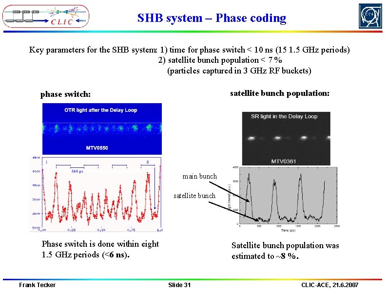
SHB system – Phase coding Key parameters for the SHB system: 1) time for phase switch < 10 ns (15 1. 5 GHz periods) 2) satellite bunch population < 7 % (particles captured in 3 GHz RF buckets) satellite bunch population: phase switch: main bunch satellite bunch Phase switch is done within eight 1. 5 GHz periods (<6 ns). Frank Tecker Satellite bunch population was estimated to ~8 %. Slide 31 CLIC-ACE, 21. 6. 2007
Delay Loop – first recombination 2005 0. 2 Satellites straight Satellites delayed beam current (A) 0 -0. 2 Beam in DL -0. 4 -0. 6 Beam in DL (delayed) Main bunches delayed Main bunches straight -0. 8 -1 -1. 2 5150 Beam before DL 5250 Beam after DL Phase switch 5350 5450 5550 5650 5750 5850 time (ns) Frank Tecker Slide 32 CLIC-ACE, 21. 6. 2007
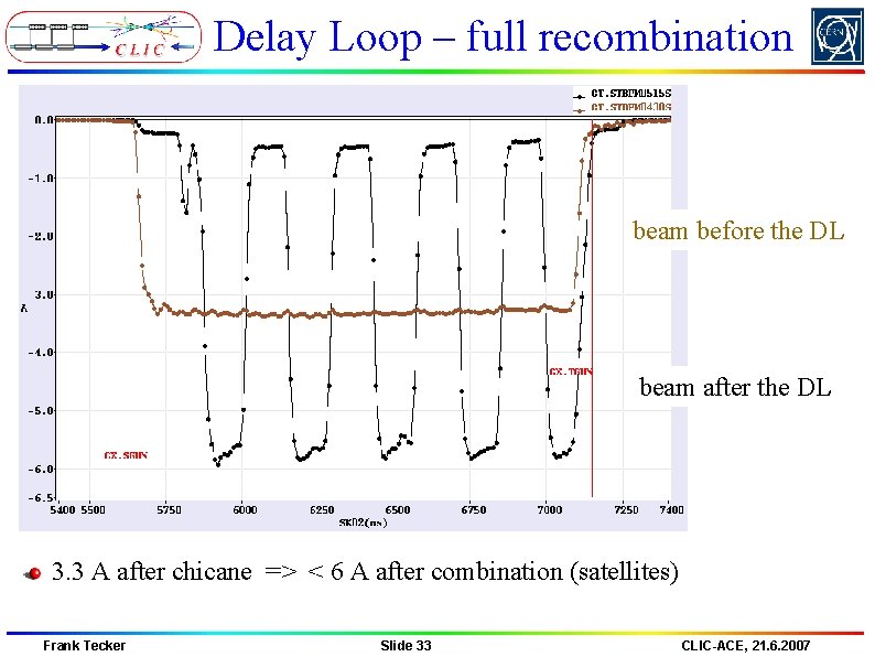
Delay Loop – full recombination beam before the DL beam after the DL 3. 3 A after chicane => < 6 A after combination (satellites) Frank Tecker Slide 33 CLIC-ACE, 21. 6. 2007
Combiner Ring Frank Tecker Slide 34 CLIC-ACE, 21. 6. 2007
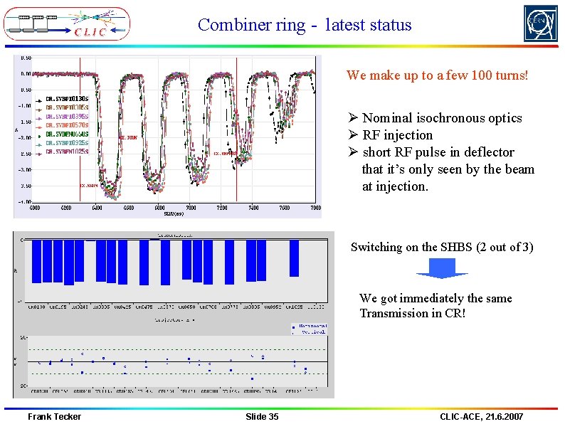
Combiner ring - latest status We make up to a few 100 turns! Ø Nominal isochronous optics Ø RF injection Ø short RF pulse in deflector that it’s only seen by the beam at injection. Switching on the SHBS (2 out of 3) We got immediately the same Transmission in CR! Frank Tecker Slide 35 CLIC-ACE, 21. 6. 2007
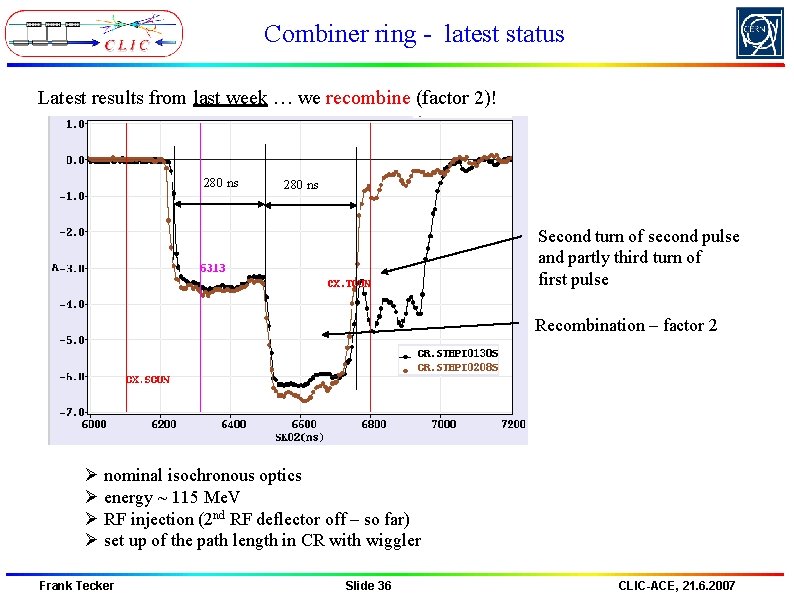
Combiner ring - latest status Latest results from last week … we recombine (factor 2)! 280 ns Second turn of second pulse and partly third turn of first pulse Recombination – factor 2 Ø nominal isochronous optics Ø energy ~ 115 Me. V Ø RF injection (2 nd RF deflector off – so far) Ø set up of the path length in CR with wiggler Frank Tecker Slide 36 CLIC-ACE, 21. 6. 2007
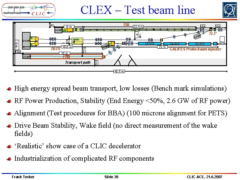
CLEX – Two beam test stand High-power test of PETS – first tests of CLIC (lengthened) prototypes 12 GHz high-power test of accelerating structures Two beam acceleration of ‘main’ beam from CALIFES Measurement of breakdown kick, breakdown current meas. planned High-power test of PETS on/off mechanism Operation of CLIC module Frank Tecker Slide 37 CLIC-ACE, 21. 6. 2007
CLEX – Test beam line 1 DUMP 8 m DFD 2. 0 m 16. 5 m 16 m DUMP F F D D F DFD F D F F FD LIL-ACS F DU D LIL-ACS 22 m F D D D F P DUM 3. 0 m DF TL 2’ LIL-ACS 2 m CALIFES Probe beam injector F ITB 1. 4 m Transport path D D F D MP 3. 0 m DF 22. 4 m F D FD DFD 2. 5 m TBTS D 1. 85 m DFD F 0. 75 DUMP TBL 6 m 42. 5 m High energy spread beam transport, low losses (Bench mark simulations) RF Power Production, Stability (End Energy <50%, 2. 6 GW of RF power) Alignment (Test procedures for BBA) (100 microns alignment for PETS) Drive Beam Stability, Wake field (no direct measurement of the wake fields) ‘Realistic’ show case of a CLIC decelerator Industrialization of complicated RF components Frank Tecker Slide 38 CLIC-ACE, 21. 6. 2007
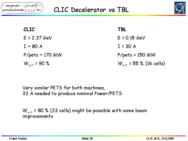
CLIC Decelerator vs TBL CLIC TBL E = 2. 37 Ge. V E = 0. 15 Ge. V I ~ 80 A I = 30 A P/pets ~ 170 MW P/pets = 150 MW Wext = 90 % Wext = 55 % (16 cells) Very similar PETS for both machines, 32 A needed to produce nominal Power/PETS Wext = 80 % (23 cells) might be possible with some beam improvements Frank Tecker Slide 39 CLIC-ACE, 21. 6. 2007
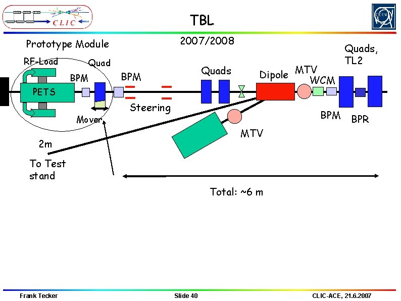
TBL 2007/2008 Prototype Module RF-Load Quad BPM Quads BPM PETS Mover Dipole MTV WCM Steering BPM Quads, TL 2 BPR MTV 2 m To Test stand Total: ~6 m Frank Tecker Slide 40 CLIC-ACE, 21. 6. 2007
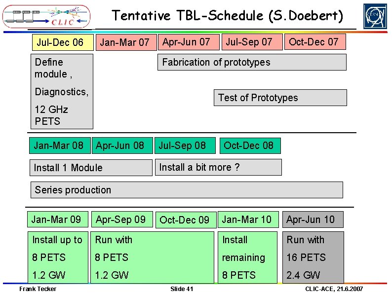
Tentative TBL-Schedule (S. Doebert) Jul-Dec 06 Jan-Mar 07 Define module , Apr-Jun 07 Jul-Sep 07 Oct-Dec 07 Fabrication of prototypes Diagnostics, Test of Prototypes 12 GHz PETS Jan-Mar 08 Apr-Jun 08 Install 1 Module Jul-Sep 08 Oct-Dec 08 Install a bit more ? Series production Jan-Mar 09 Apr-Sep 09 Install up to Jan-Mar 10 Apr-Jun 10 Run with Install Run with 8 PETS remaining 16 PETS 1. 2 GW 8 PETS 2. 4 GW Frank Tecker Oct-Dec 09 Slide 41 CLIC-ACE, 21. 6. 2007
Conclusion fully loaded operation demonstrated and routinely used bunch train combination principle shown (Prel. Phase) phase coding of bunches and full current DL operation full current CR combination on a good way => fully loaded drive beam generation well covered extensive high power RF testing (now automated) different tests in CLEX from 2008 Frank Tecker Slide 42 CLIC-ACE, 21. 6. 2007