LAr 1 ND David Montanari Fermi National Accelerator


- Slides: 26

LAr 1 -ND David Montanari Fermi National Accelerator Laboratory dmontana@fnal. gov CERN – Feb 16, 2014

Outline • • Introduction Requirements Location Cryostat Cryogenic system Open issues Q&A Summary LAr 1 -ND Meeting – Feb 16, 2014 – CERN 2

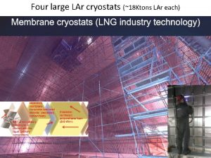
Introduction • The design of LAr 1 -ND builds on many years of LAr TPC detector R&D and experience from design and construction of ICARUS T 600, Argo. Neut, Micro. Boo. NE and LBNE 35 ton. • Membrane cryostat technology with passive insulation (Polyurethane foam). See previous talk for details. • Where: Fermilab • Location: Sci. Boo. NE enclosure, on-axis at 100 m from the Booster Neutrino Beam target. LAr 1 -ND Meeting – Feb 16, 2014 – CERN 3

Requirements • Purity: 10 ms electron lifetime (< 30 ppt O 2 equivalent contamination). • High reliability of the LN 2 cooling system (value? ? ). • Avoid, if possible, purification of the bulk of the liquid. See purity requirement. LAr 1 -ND Meeting – Feb 16, 2014 – CERN 4

Cryostat LAr 1 -ND Meeting – Feb 16, 2014 – CERN 5

Current Design Parameters Parameter Value Type of structure Membrane cryostat inside an existing concrete pit (already capable of withstanding the hydrostatic pressure) Cryostat Volume 108 m^3 Liquid Argon total mass 150 ton Inner dimensions of cryostat 4. 4 m (L) x 5. 1 m (W) x 4. 8 m (H) Depth of liquid argon 4. 8 m (no ullage, but expansion tank on the top) Insulation 0. 25 m (bottom), 0. 40 m (top) 0. 45 m (beam left/right), 0. 20 m (beam upstream/downstream) Primary membrane 1. 2 mm SS 304 L (if GTT) or 2. 0 mm SS 304 (if IHI) Outside reinforcement Existing concrete pit Operating gas pressure 1. 0 psig (~70 mbar) Vacuum No vacuum Design pressure 3. 0 psig (~207 mbar) Heal Leak (reduced by LN 2 cooling plates attached to the membrane). ~2. 5 k. W (Cryostat) + ~0. 5 (Electronics) + ~0. 5 (feedthrus) Total: ~3. 6 k. W Duration 10 years Thermal cycles 10 complete cycles (cool down and total warm up) LAr 1 -ND Meeting – Feb 16, 2014 – CERN 6

8, 534 mm 3, 048 mm Location: Sci. Boo. NE detector hall Beam 4, 900 mm LAr 1 -ND Meeting – Feb 16, 2014 – CERN 7

Side Views Expansion Tank HV Feedthrough Signal Feedthrough Expansion Tank Installation Hatch 4, 800 mm Insulation 400 mm Beam Insulation 200 mm 2, 130 mm Insulation 250 mm LAr 1 -ND Meeting – Feb 16, 2014 – CERN Insulation 450 mm Insulation 250 mm 8

Insulation 200 mm 4, 400 mm 4, 900 mm Insulation 450 mm Top view Insulation 200 mm 1, 000 mm 5, 100 mm LAr 1 -ND Meeting – Feb 16, 2014 – CERN 9

Cryogenic System LAr 1 -ND Meeting – Feb 16, 2014 – CERN 10

Cryogenic System – 1 If possible, the goal is to not purify the bulk of the liquid during regular operations, but only the boil off gas. The idea is to fill the membrane cryostat completely and reach the expansion tank with the liquid to minimize the outgassing to that region only. (No outgassing in the liquid). • To purify the LAr during the initial filling via molecular sieve and copper beds to remove respectively water and oxygen. • To purify and recondense (or vice versa) the boil off gas from the expansion tank using molecular sieve and copper beds: • It may be necessary to suck the boil off gas in order to overcome the outgassing flow rate in the expansion tank. • It may be possible to use the same purification system used during the LAr filling. • To purify the bulk of the LAr, if needed. • LAr pumps (where? ? ). • To handle the LAr/GAr and LN 2/GN 2 flows: • Cleaning GAr purging and venting, GAr recirculation and purification. • Ops cool down, LAr filling, GAr boil off purification and re-condensation, LAr return to the tank. LAr 1 -ND Meeting – Feb 16, 2014 – CERN 11

Cryogenic System – 2 • To recondense the boil off gas: • LAr condenser and LN 2 phase separator. • Pressure control: • PSV, VSV, Auto/Manual venting. • To handle the LN 2/GN 2 flow to/from the heat exchanger panels inside the membrane cryostat. • To handle the GAr purge inside the insulation. • Instrumentation and diagnostics: T and P sensors, flow meters, etc. , Analytical instruments to measure the contamination, in-line Purity Monitors? , etc. • To develop the control system. LAr 1 -ND Meeting – Feb 16, 2014 – CERN 12

Open issues – 1 Expansion tank: • Is it technically possible to design a zero-ullage tank with all the gas in n expansion tank? • Is feasible to reduce the contamination in the bulk of the liquid by raising the level of the liquid to the expansion tank? • Should it be designed like an extension of the membrane cryostat rather than a stand-alone tank connected to the membrane cryostat? Like 35 ton chimney but taller to allow ~5% of gas region. LAr 1 -ND Meeting – Feb 16, 2014 – CERN 13

Open issues – 1 Warm FT al la Micro. Boo. NE Integrated expansion volume Liquid Level Liquid Argon – TPC In Here Cables and services – routed via a small opening in the membrane Insulation LAr 1 -ND Meeting – Feb 16, 2014 – CERN 14

Open issues – 2 Cold Feedthrough: • Are they really necessary? • Is it the right technical choice? LAr 1 -ND Meeting – Feb 16, 2014 – CERN 15

Open issues – 3 Purification/Filtration system(s): • • How many are needed? Gas recirculation: GAr purification during initial cleaning. Filling: LAr purification. Ops: GAr boil off purification and no LAr purification (idea). • • Liquid phase: condense and then purify before sending back to the tank? Gas phase: purify and then condense before sending back to the tank? • Is it feasible to purify the LAr at the beginning during the filling and no more, just the boil off GAr? • What is the outgassing rate from the “warm”/gas region? Does it match the boil off rate or do we have to pull GAr to overcome the outgassing? If so, how? Pump? • Will the bulk of the liquid be pure enough if it is not continuously purified? Or will it need to be purified as well? • What kind of LAr/GAr purification system? • • Mol sieve + Copper beds Are there more types of mol sieves? LAr 1 -ND Meeting – Feb 16, 2014 – CERN 16

Open issues – 4 LAr pumps: • Ideal: outside. • With membrane cryostats it is not possible: all penetrations are on top of the tank. • Submerged in LAr. • How do we protect against failures? • Submerged with retraction system and foot valve: • • • Can be pulled out for maintenance and reinstated inside without emptying the tank nor contaminating the liquid. The foot valve closes before the extraction isolating the pump tower from the tank. Standard commercial solution for LNG tanks. If continuous LAr filtration is needed, this solution requires an additional pump for the downtime of maintenance of the first pump. More expensive. Current choice for LBNE-FD. • Alternatives? LAr 1 -ND Meeting – Feb 16, 2014 – CERN 17

Open issues – 4 LAr 1 -ND Meeting – Feb 16, 2014 – CERN 18

Open issues – 5 Installation of TPCs: • How will the TPCs be installed? • Do the cryostat dimensions need to be revised to account for the installation of the TPCs? • Does the location of the openings (feedthroughs and installation hatch) need to be modified? LAr 1 -ND Meeting – Feb 16, 2014 – CERN 19

Q&A – 1 1) Heating power that has to be adsorbed (including feedthroughs, etc. )? • • Feedthroughs and digital electronics 0. 6 k. W. (BY/CT). Membrane cryostat ~2. 5 k. W. (BY/CT). Assuming for feedthroughs and plumbing: 0. 5 k. W (assumption BY/CT). Total: ~3. 6 k. W. 2) At which temperature will the "warm" gas arrive in the cooling system and at which temperature shall the "liquefied" gas leave the cooling system? • • Gas will be at ~100 K. (BY/CT). Return liquid at ~89 K. (BY/CT). 3) Shall a purification system be foreseen for the installation: purification in gaseous phase (=warm), or purification in liquid phase (cold)? • See Open Issue n. 3. LAr 1 -ND Meeting – Feb 16, 2014 – CERN 20

Q&A – 2 4) Since the re-condensation probably has to happen outside the cryostat: would a liquid argon circulator be acceptable to circulate the argon in liquid phase through a purifier? • • • We propose to use heat-exchange panels in the cryostat, on the surfaces, cooled with pressurized LN 2, to remove the bulk of the heat; the remainder will evaporate sufficient liquid to ensure adequate purification of the gas to maintain the required purity. (BY/CT). After an initial gas cool down to ~90 K, liquid would be introduced through the purifier and recirculated through the purifier until the cryostat is filled. (BY/CT). There should be condensation of the boil off gas in a condenser outside the cryostat. (DM). 5) How shall the re-condensed liquid be returned to the cryostat (eventual movements in the argon bath)? • It can be returned to the bulk of the cryostat few inch from the floor via vacuum insulated pipe. (DM). 6) What will be the estimated running time of the experiment (in years)? • • At least 1 is contemplated to overlap the Micro. Boo. NE program, and hopefully 2 -3 if construction is completed well before the end of Micro. Boo. NE operations, but probably 10 if LAr 1 -FD or equivalent is constructed. (BY/CT). For design purpose 10 years suggested. The membrane manufacturer needs this information. (DM). LAr 1 -ND Meeting – Feb 16, 2014 – CERN 21

Q&A – 3 7) What are the limits for the cool down and the warm-up of the system to be cooled? • • • The cool down rate should be slow enough to ensure <20 K difference between the TPC sense wires and APA frame. The warm up rate is much less restricted. (BY/CT). The manufacturer of the membrane cryostat has lower limits on the cool down: IHI’s max cool down rate for the membrane is 20 K/hr (same). (DM). Suggested 15 K/hr between room and 190 K and 10 K/hr from 190 K to LAr temperature. (DM). 8) Q: How often shall a cool-down / warm-up of the system be foreseen: • • • Once or twice in the presently conceived operating plan; more if other plans for the system are developed. (BY/CT). There at present no plans to store the LAr, although if several cycles of filling are contemplated, a storage vessel might be economic. (BY/CT). A LAr pump is incorporated in the cryogenic system to empty the vessel. There is the desire to put the LAr pump outside, but that will not be possible, as no side penetrations are allowed through the membrane. The LAr pump will have to be submerged. (DM). 9) Will the system be installed in an area where there could be an oxygen shortage problem for personnel? • Yes, probably ODH 0 (free access) or ODH 1 (restricted access, but no protective equipment). (BY/CT). LAr 1 -ND Meeting – Feb 16, 2014 – CERN 22

Q&A – 4 10) What should be the level of reliability of the cryogenic system (defines the eventual back-up systems)? • The LN 2 cooling system should be very reliable to avoid loss of Ar. The purification system is less constrained. (BY/CT). LAr 1 -ND Meeting – Feb 16, 2014 – CERN 23

Potential synergies • Fermilab has technical and business expertise in Membrane Cryostat technology (35 ton prototype). • Fermilab and CERN have technical expertise in Cryogenic Systems. Engineering, Construction, Commissioning of Cryogenic System Sharing expertise and collaborate on Cryogenics for LAr experiments (LAr-1 -ND, LBNE-FD, WA-104, WA-105, etc. ) LAr 1 -ND Meeting – Feb 16, 2014 – CERN 24

Summary • LAr 1 -ND proposes to use the membrane cryostat technology for a new onaxis Near Detector using the R&D and experience from the design and construction of similar LAr-TPC detectors. • It presents several innovative aspects: – The absence of the ullage and the use of an expansion tank on top. – The use of cold feedthroughs. – The idea of purifying only the boil off GAr form the expansion tank during operations and not the bulk of the liquid. – The use of LN 2 cooled heat exchange panels inside the tank to cool-down the LAr trying to minimize boil-off. • Fermilab and CERN have great expertise in cryogenic systems. It would be very valuable to share expertise and collaborate on the development, design and construction of cryogenic systems for liquid Argon detectors, starting from LAr 1 -ND where CERN could provide a significant contribution. LAr 1 -ND Meeting – Feb 16, 2014 – CERN 25

Thanks LAr 1 -ND Meeting – Feb 16, 2014 – CERN
 Www.liceomontanari.it
 Alberto montanari
 Claudia montanari radiata
 Wallace 9'lar kuralı
 Casamento significado espiritual
 Nuklein kislotalar ppt
 Fosfodiefir bog'lar haqida
 Temuriylar davri madaniyati
 Aylanma fondlar
 Lar routing protocol
 Hmda & cra data integrity reviews
 Lar surgery
 Qiymetlendirme meyarlari
 Yevrosiyo materigi
 Lar lər çoxluq bildirən hissəcik
 Parkland formülü
 Yanık yüzdesi hesaplama 9'lar kuralı
 Vad är tumgreppet
 Nascestes no lar que precisavas
 Lar stavanger
 Temas para evangelho no lar
 Lar fabiano de cristo
 Tenho ouvido de uma terra linda encantada
 Yanık yüzdesi hesaplama 9'lar kuralı
 To'pgullar va ularning klassifikatsiyasi
 Lar de tereza
 Lar 40
