
LAr 40 Cold Electronics WBS 130 05 03
LAr 40 Cold Electronics WBS 130. 05. 03. 04 Craig Thorn 1 Far Site Review, December 6 -9, 2011
Outline � Scope & Requirements � Electronics specifications � Technical overview � Data rates � Zero-suppression � Electronics overview � Front-end (analog) ASIC � Digital (ADC, buffer, mux) ASIC � Cryogenic operation of CMOS ASICs � Electronics details and specifications � Schedule � Summary 2 Far Site Review, December 6 -9, 2011 Craig Thorn
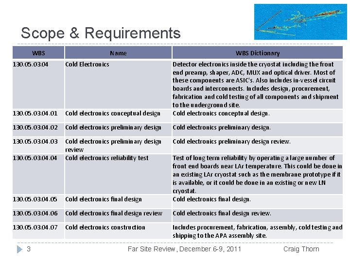
Scope & Requirements WBS Name WBS Dictionary Can use WBS definitions (http: //lbne 2130. 05. 03. 04 Cold Electronics Detector electronics inside the cryostat including the front docdb. fnal. gov: 8080/cgi- end preamp, shaper, ADC, MUX and optical driver. Most of these components are ASIC's. Also includes in-vessel circuit bin/Show. Document? docid=2163) for scope. Note boards and interconnects. Includes design, procurement, fabrication and cold testing of all components and shipment that WBS#’s are out of date, also be sure text to the underground site. 130. 05. 03. 04. 01 Cold electronics conceptual design reflects current reference Cold electronics conceptual design choice. 130. 05. 03. 04. 02 Cold electronics preliminary design. � Requirements: Get from Anne Heavey, DOORS 130. 05. 03. 04. 03 Cold electronics preliminary design review output. (http: //lbne 2 -docdb. fnal. gov: 8080/cgi 130. 05. 03. 04 Cold electronics reliability test Test of long term reliability by operating a large number of front end boards near LAr temperature. This could be done in bin/Show. Document? docid=3747) Anne should have an existing LAr cryostat such as the membrane prototype if it the outputs by Dec. 1 st. ) is available, or it could be done in an existing or new LN � Scope: 130. 05. 03. 04. 05 Cold electronics final design cryostat. Cold electronics final design. 130. 05. 03. 04. 06 Cold electronics final design review. 130. 05. 03. 04. 07 Cold electronics construction Includes procurement, fabrication, assembly, cold testing and shipping to the APA assembly site. 3 Far Site Review, December 6 -9, 2011 Craig Thorn
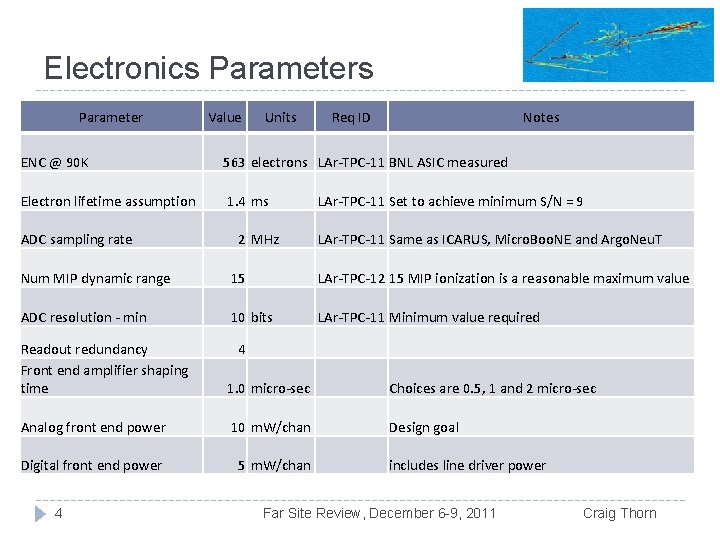
Electronics Parameter Value Units Req ID Notes ENC @ 90 K 563 electrons LAr-TPC-11 BNL ASIC measured Electron lifetime assumption 1. 4 ms ADC sampling rate 2 MHz LAr-TPC-11 Set to achieve minimum S/N = 9 LAr-TPC-11 Same as ICARUS, Micro. Boo. NE and Argo. Neu. T Num MIP dynamic range 15 LAr-TPC-12 15 MIP ionization is a reasonable maximum value ADC resolution - min 10 bits LAr-TPC-11 Minimum value required Readout redundancy Front end amplifier shaping time 1. 0 micro-sec Choices are 0. 5, 1 and 2 micro-sec Analog front end power 10 m. W/chan Design goal Digital front end power 5 m. W/chan includes line driver power 4 4 Far Site Review, December 6 -9, 2011 Craig Thorn
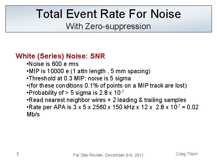
Total Event Rate For Noise With Zero-suppression White (Series) Noise: SNR • Noise is 600 e rms • MIP is 10000 e (1 attn length , 5 mm spacing) • Threshold at 0. 3 MIP: noise is 5 sigma • (for these conditions 0. 1% of points on a MIP track are lost) • Probability of > 5 sigma is 2. 8 x 10 -7 • Read nearest neighbor wires + 2 leading & trailing samples • Rate per APA is 3 x 5 x 2560 x 150 k. Hz x 12 x 2. 8 x 10 -7 = 0. 02 Mb/s 5 Far Site Review, December 6 -9, 2011 Craig Thorn
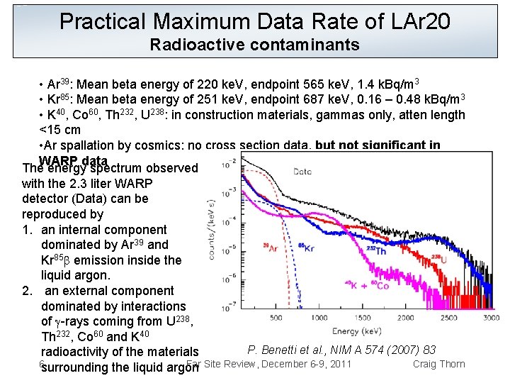
Practical Maximum Data Rate of LAr 20 Radioactive contaminants • Ar 39: Mean beta energy of 220 ke. V, endpoint 565 ke. V, 1. 4 k. Bq/m 3 • Kr 85: Mean beta energy of 251 ke. V, endpoint 687 ke. V, 0. 16 – 0. 48 k. Bq/m 3 • K 40, Co 60, Th 232, U 238: in construction materials, gammas only, atten length <15 cm • Ar spallation by cosmics: no cross section data, but not significant in WARP data The energy spectrum observed with the 2. 3 liter WARP detector (Data) can be reproduced by 1. an internal component dominated by Ar 39 and Kr 85 b emission inside the liquid argon. 2. an external component dominated by interactions of g-rays coming from U 238, Th 232, Co 60 and K 40 P. Benetti et al. , NIM A 574 (2007) 83 radioactivity of the materials 6 surrounding the liquid argon Far Site Review, December 6 -9, 2011 Craig Thorn
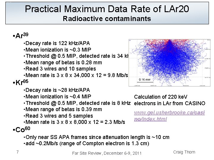
Practical Maximum Data Rate of LAr 20 Radioactive contaminants • Ar 39 • Decay rate is 122 k. Hz/APA • Mean ionization is ~0. 3 MIP • Threshold @ 0. 5 MIP, detected rate is 34 k. Hz • Mean range of betas is 0. 28 mm • Read 3 wires and 10 samples • Mean rate is 3 x 8 x 34, 000 x 12 = 9. 8 Mb/s • Kr 85 • Decay rate is ~28 k. Hz/APA • Mean ionization is ~0. 4 MIP • Threshold @ 0. 5 MIP, detected rate is 8 k. Hz • Mean range of betas is 0. 39 mm • Read 3 wires and 5 samples • Mean rate is 3 x 8, 000 x 12 = 2. 3 Mb/s Calculation of 220 ke. V electrons in LAr from CASINO www. gel. usherbrooke. ca/casi no/index. html • Co 60 • Only near SS APA frames since attenuation length is ~10 cm • add ~0. 2 Mb/s (range of Compton electron is 1. 3 cm) 7 Far Site Review, December 6 -9, 2011 Craig Thorn
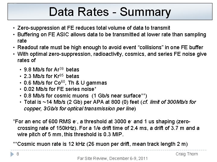
Data Rates - Summary • Zero-suppression at FE reduces total volume of data to transmit • Buffering on FE ASIC allows data to be transmitted at lower rate than sampling rate • Readout rate must be high enough to avoid event “collisions” in one FE buffer • With optimal zero-suppression, radioactivity, cosmics, and series FE noise give rates of • • • 9. 8 Mb/s for Ar 39 betas 2. 3 Mb/s for Kr 85 betas 0. 6 Mb/s for Co 60, Th & U gammas 0. 02 Mb/s for FE series noise* 0. 8 Mb/s for cosmic muons (1 Gb/s near surface**) Total is ~14 Mb/s (2 Gb) per APA at 800 (0) feet (cf. limit of 300 Mb/s for copper, 3 Gb/s for optical transmission per line) *For an enc of 600 RMS e-, a threshold at 3000 e- and 1 us shaping (zerocrossing rate of 150 k. Hz). For a 1/e drift time of 2. 4 ms, a drift of 3. 7 m and a wire pitch of 5 mm, this threshold is 0. 3 MIP. **Cosmic muon rate is 12 k. Hz (26 muon per drift, mean track length 2 m) 8 Far Site Review, December 6 -9, 2011 Craig Thorn
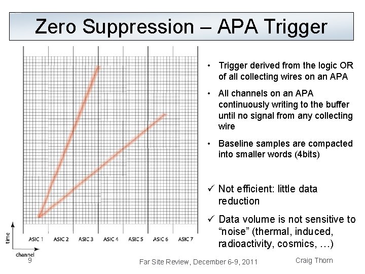
Zero Suppression – APA Trigger • Trigger derived from the logic OR of all collecting wires on an APA • All channels on an APA continuously writing to the buffer until no signal from any collecting wire • Baseline samples are compacted into smaller words (4 bits) ü Not efficient: little data reduction ü Data volume is not sensitive to “noise” (thermal, induced, radioactivity, cosmics, …) 9 Far Site Review, December 6 -9, 2011 Craig Thorn
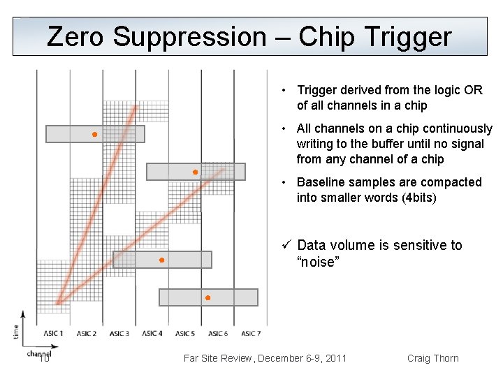
Zero Suppression – Chip Trigger • Trigger derived from the logic OR of all channels in a chip • All channels on a chip continuously writing to the buffer until no signal from any channel of a chip • Baseline samples are compacted into smaller words (4 bits) ü Data volume is sensitive to “noise” 10 Far Site Review, December 6 -9, 2011 Craig Thorn
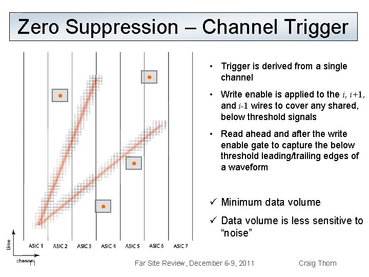
Zero Suppression – Channel Trigger • Trigger is derived from a single channel • Write enable is applied to the i, i+1, and i-1 wires to cover any shared, below threshold signals • Read ahead and after the write enable gate to capture the below threshold leading/trailing edges of a waveform ü Minimum data volume ü Data volume is less sensitive to “noise” 11 Far Site Review, December 6 -9, 2011 Craig Thorn
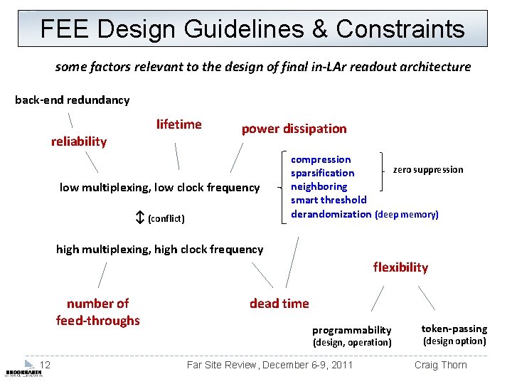
FEE Design Guidelines & Constraints some factors relevant to the design of final in-LAr readout architecture back-end redundancy lifetime reliability power dissipation low multiplexing, low clock frequency ↕ (conflict) compression zero suppression sparsification neighboring smart threshold derandomization (deep memory) high multiplexing, high clock frequency flexibility number of feed-throughs dead time programmability (design, operation) 12 Far Site Review, December 6 -9, 2011 token-passing (design option) Craig Thorn
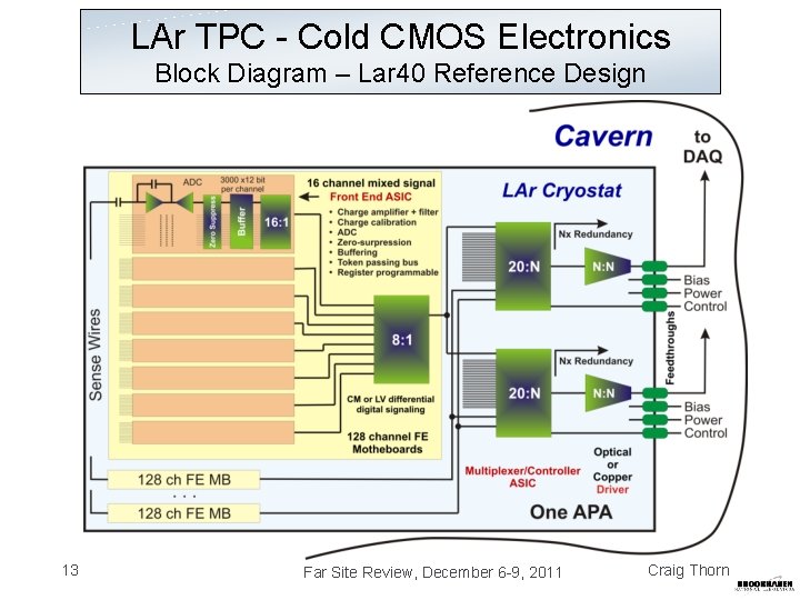
LAr TPC - Cold CMOS Electronics Block Diagram – Lar 40 Reference Design 13 Far Site Review, December 6 -9, 2011 Craig Thorn
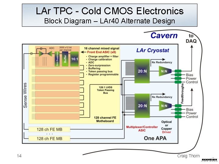
LAr TPC - Cold CMOS Electronics Block Diagram – LAr 40 Alternate Design 14 Far Site Review, December 6 -9, 2011 Craig Thorn
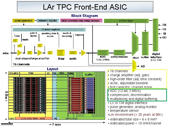
LAr TPC Front-End ASIC • 16 channels • charge amplifier (adj. gain) • high-order filter (adj. time constant) • ac/dc, adjustable baseline • test capacitor, channel mask • ADC (12 -bit, 2 MS/s) • compression, discrimination • multiplexing and digital buffering • LV or CM digital interface • pulse generator, analog monitor • temperature sensor • LAr environment (> 20 years at 88 K) • estimated total size ~ 6 x 8 mm² • estimated power ~ 10 m. W/channel
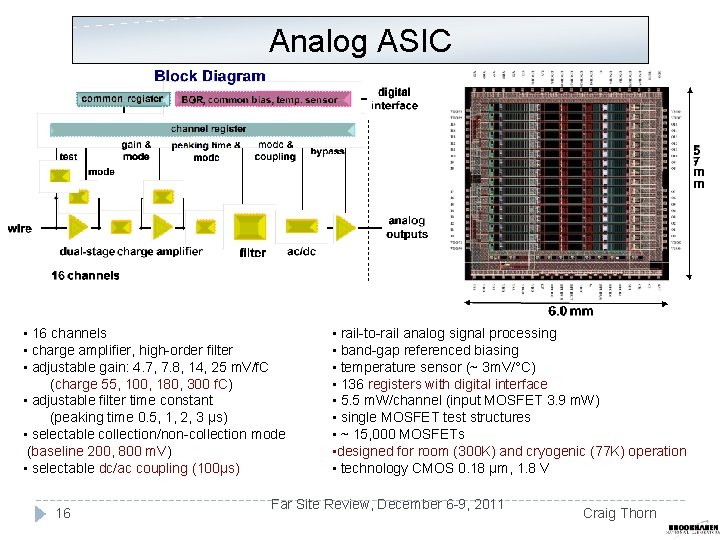
Analog ASIC • 16 channels • charge amplifier, high-order filter • adjustable gain: 4. 7, 7. 8, 14, 25 m. V/f. C (charge 55, 100, 180, 300 f. C) • adjustable filter time constant (peaking time 0. 5, 1, 2, 3 µs) • selectable collection/non-collection mode (baseline 200, 800 m. V) • selectable dc/ac coupling (100µs) 16 • rail-to-rail analog signal processing • band-gap referenced biasing • temperature sensor (~ 3 m. V/°C) • 136 registers with digital interface • 5. 5 m. W/channel (input MOSFET 3. 9 m. W) • single MOSFET test structures • ~ 15, 000 MOSFETs • designed for room (300 K) and cryogenic (77 K) operation • technology CMOS 0. 18 µm, 1. 8 V Far Site Review, December 6 -9, 2011 Craig Thorn

Signal Measurements Bandgap Reference variation ≈ 1. 8 % Temperature Sensor ~ 2. 86 m. V / °K Pole-zero cancellation at 77 K to be addressed in next revision Adjustable gain, peaking time and baseline 17 maximum charge 55, 100, 180, 300 f. C Far Site Review, December 6 -9, 2011
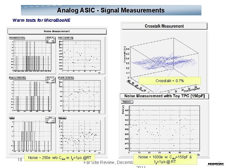
Analog ASIC - Signal Measurements Warm tests for Micro. Boo. NE Crosstalk < 0. 7% 18 Noise < 1000 e- w. Cdet=150 p. F & tp=1μs @ RT Far Site Review, December 6 -9, Noise ~ 250 e- w/o Cdet w. tp=1μs @RT
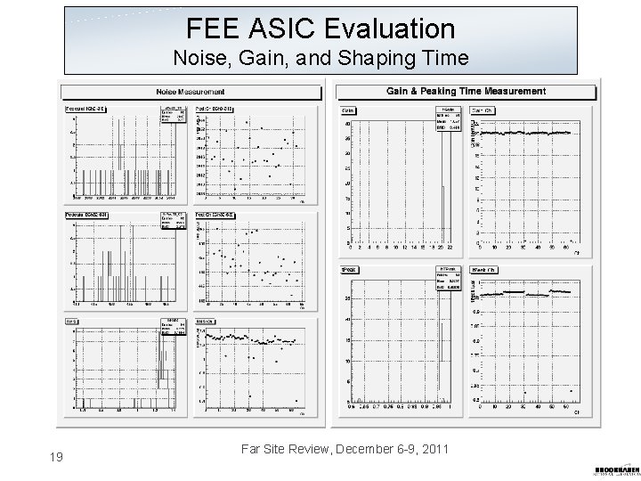
FEE ASIC Evaluation Noise, Gain, and Shaping Time 19 Far Site Review, December 6 -9, 2011
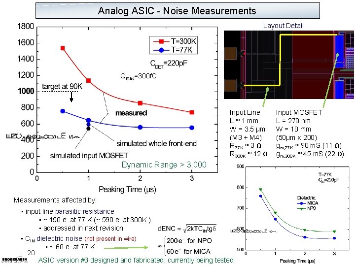
Analog ASIC - Noise Measurements Layout Detail Qmax=300 f. C Input Line L ≈ 1 mm W = 3. 5 µm (M 3 + M 4) R 77 K ≈ 3 Ω R 300 K ≈ 12 Ω Dynamic Range > 3, 000 Measurements affected by: • input line parasitic resistance • ~ 150 e- at 77 K (~ 590 e- at 300 K ) • addressed in next revision • CIN dielectric noise (not present in wire) • ~ 60 e- at 77 K 20 ASIC version #3 designed and fabricated, currently being tested Input MOSFET L = 270 nm W = 10 mm (50µm x 200) gm, 77 K ≈ 90 m. S (11 Ω) gm, 300 K ≈ 45 m. S (22 Ω)
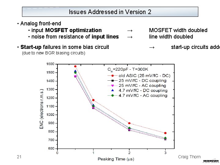
Issues Addressed in Version 2 • Analog front-end • input MOSFET optimization • noise from resistance of input lines • Start-up failures in some bias circuit → → MOSFET width doubled line width doubled → start-up circuits adde (due to new BGR biasing circuits) 21 Craig Thorn
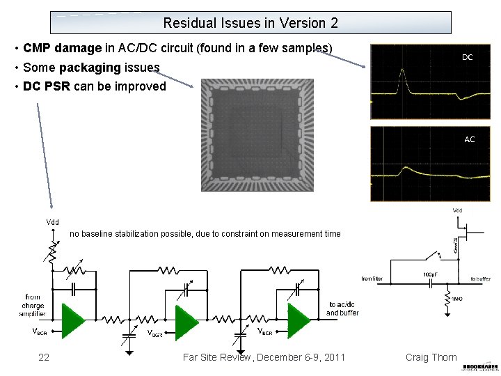
Residual Issues in Version 2 • CMP damage in AC/DC circuit (found in a few samples) • Some packaging issues • DC PSR can be improved no baseline stabilization possible, due to constraint on measurement time 22 Far Site Review, December 6 -9, 2011 Craig Thorn
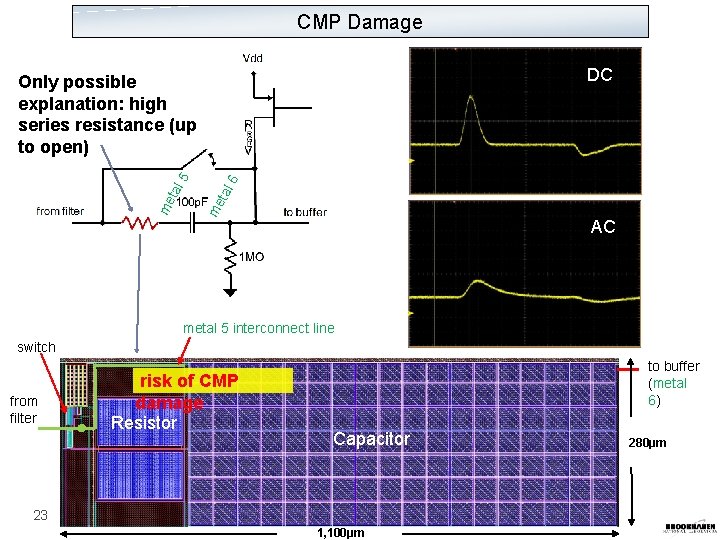
CMP Damage DC 6 tal me me tal 5 Only possible explanation: high series resistance (up to open) AC metal 5 interconnect line switch from filter risk of CMP damage Resistor to buffer (metal 6) Capacitor 23 1, 100µm 280µm
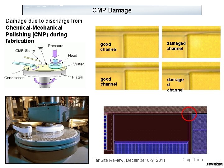
CMP Damage due to discharge from Chemical-Mechanical Polishing (CMP) during fabrication 24 DC good channel damaged channel good channel damage d channel Far Site Review, December 6 -9, 2011 Craig Thorn
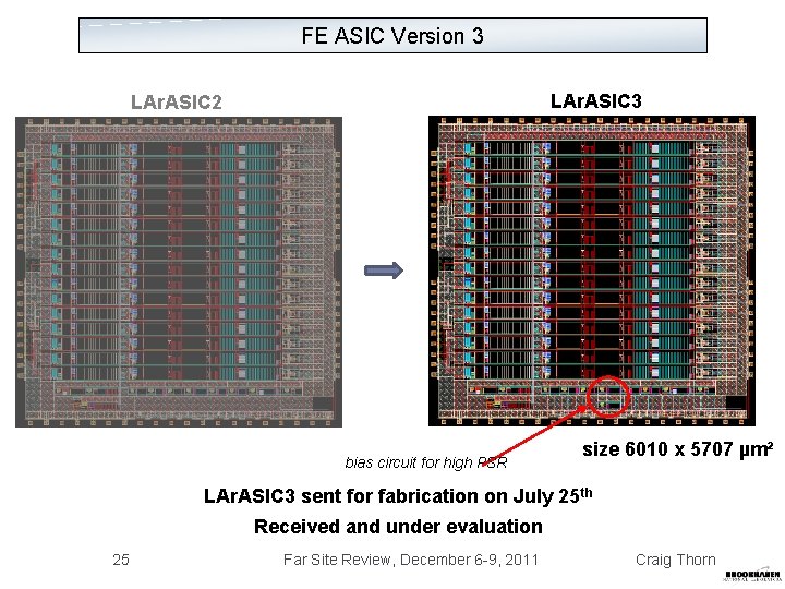
FE ASIC Version 3 LAr. ASIC 2 bias circuit for high PSR size 6010 x 5707 µm² LAr. ASIC 3 sent for fabrication on July 25 th Received and under evaluation 25 Far Site Review, December 6 -9, 2011 Craig Thorn
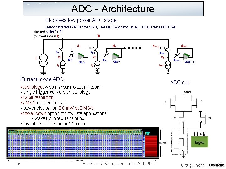
ADC - Architecture Clockless low power ADC stage Demonstrated in ASIC for SNS, see De Geronimo, et al. , IEEE Trans NSS, 54 (2007) 541 Current mode ADC • dual stage 6 -MSBs in 150 ns, 6 -LSBs in 250 ns • single trigger conversion per stage • 12 -bit resolution • 2 MS/s conversion rate • power dissipation 3. 6 m. W at 2 MS/s • power-down option for low rate applications • wake up in few tens of ns • layout size: 0. 23 mm x 1. 25 mm 26 Far Site Review, December 6 -9, 2011 ADC cell Craig Thorn
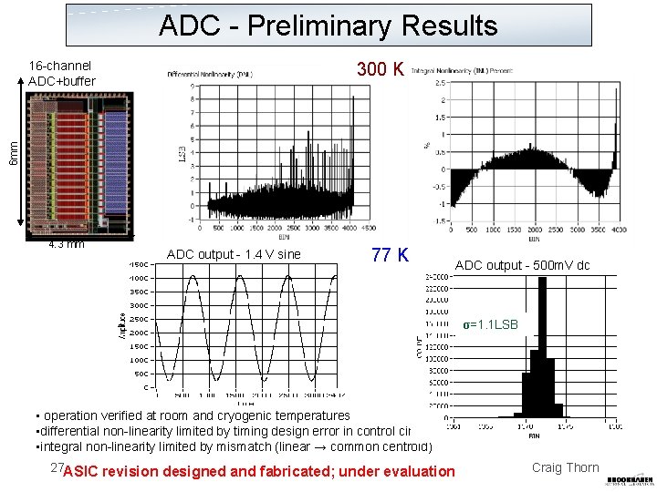
ADC - Preliminary Results 16 -channel ADC+buffer 6 mm 300 K 4. 3 mm ADC output - 1. 4 V sine 77 K ADC output - 500 m. V dc σ=1. 1 LSB • operation verified at room and cryogenic temperatures • differential non-linearity limited by timing design error in control circuit • integral non-linearity limited by mismatch (linear → common centroid) 27 ASIC revision designed and fabricated; under evaluation Craig Thorn
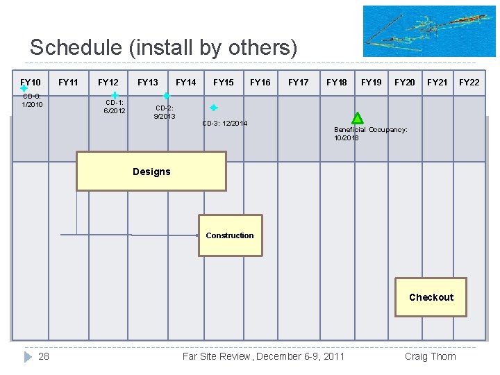
Schedule (install by others) FY 11 FY 12 � Schedule FY 10 CD-0: 1/2010 CD-1: 6/2012 FY 13 FY 14 provided by. FY 15 Ken. FY 16 CD-2: 9/2013 CD-3: 12/2014 FY 17 FY 18 FY 19 FY 20 FY 21 Beneficial Occupancy: 10/2018 Designs Construction Checkout 28 Far Site Review, December 6 -9, 2011 Craig Thorn FY 22
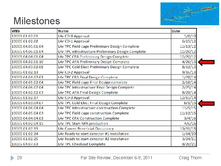
Milestones 29 Far Site Review, December 6 -9, 2011 Craig Thorn
Summary • • • CMOS performs better at cryogenic temperatures Defined and predictable design for cryogenic T is possible Low-noise at cryogenic T demonstrated • • 30 ENC < 1, 000 e- at 200 p. F ~5 m. W/ch. characterization and modeling of CMOS 180 nm • • Long lifetime at cryogenic T possible with guidelines Critical building blocks - front-end & ADC - developed • Future work • Improve cryogenic static models • Optimize ADC • Merge, add zero-suppression & buffering, and finalize Far Site Review, December 6 -9, 2011 Craig Thorn
Backup Information 31 Far Site Review, December 6 -9, 2011
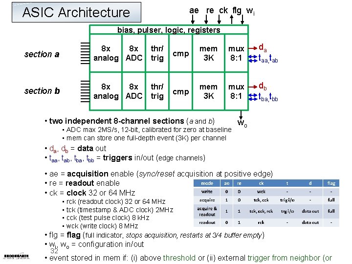
ASIC Architecture ae re ck flg wi bias, pulser, logic, registers section a 8 x 8 x analog ADC thr/ trig cmp mem 3 K mux 8: 1 da taa, tab section b 8 x 8 x analog ADC thr/ trig cmp mem 3 K mux 8: 1 db tba, tbb • two independent 8 -channel sections (a and b) • ADC max 2 MS/s, 12 -bit, calibrated for zero at baseline • mem can store one full-depth event (3 K) per channel wo • da, db = data out • taa, tab, tba, tbb = triggers in/out (edge channels) • ae = acquisition enable (sync/reset acquisition at positive edge) • re = readout enable • ck = clock 32 or 64 MHz • rck (readout clock) 32 or 64 MHz • tck (timestamp & ADC clock) 2 MHz • cck (test pulse clock) 8 k. Hz • wck (write clock) 8 MHz • flg = flag (full indicator, stops acquisition, restarts at 3/4 buffer empty) • wi, wo = configuration in/out 32 • event stored in mem if: (i) above threshold or (ii) external trigger from neighbor (or
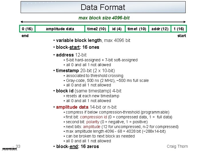
Data Format max block size 4096 -bit 0 (16) end amplitude data time 2 (10) id (4) time 1 (10) • variable block length, max 4096 bit • block-start: 16 ones addr (12) 1 (16) start • address 12 -bit • 5 -bit hard-assigned + 7 -bit soft-assigned • all 0 and all 1 not allowed • timestamp 20 -bit (2 x 10 -bit) • associated to threshold crossing • Gray-code, 500 ns (2 MHz), ~500 ms full scale • all 0 and all 1 not allowed • block id (same timestamp) 4 -bit • resets at each new timestamp • all 0 and all 1 not allowed • amplitude data 14 -bit or n-bit 33 • compress if below compression-threshold (programmable) • first bit: compression id (0 = compressed data, 1 = full data) • second bit: polarity (0 = negative, 1 = positive) • next bits: amplitude (12 for uncompressed, n-2 for compressed) • max amplitude length 4096 - 68 = 4028 bit (~288 x 14 -bit) • can be broken to next block as needed • all 0 and all 1 not allowed Craig Thorn • block-end: 16 zeros
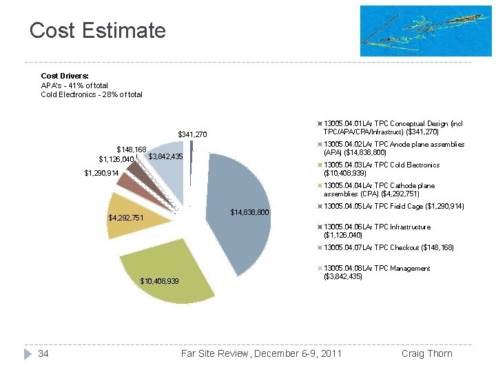
Cost Estimate Cost Drivers: APA's - 41% of total Cold Electronics - 28% of total 13005. 04. 01 LAr TPC Conceptual Design (incl TPC/APA/CPA/Infrastruct) ($341, 270) $341, 270 13005. 04. 02 LAr TPC Anode plane assemblies (APA) ($14, 838, 800) $148, 168 $3, 842, 435 $1, 126, 040 13005. 04. 03 LAr TPC Cold Electronics ($10, 408, 939) $1, 290, 914 13005. 04 LAr TPC Cathode plane assemblies (CPA) ($4, 292, 751) $4, 292, 751 $14, 838, 800 13005. 04. 05 LAr TPC Field Cage ($1, 290, 914) 13005. 04. 06 LAr TPC Infrastructure ($1, 126, 040) 13005. 04. 07 LAr TPC Checkout ($148, 168) $10, 408, 939 34 13005. 04. 08 LAr TPC Management ($3, 842, 435) Far Site Review, December 6 -9, 2011 Craig Thorn
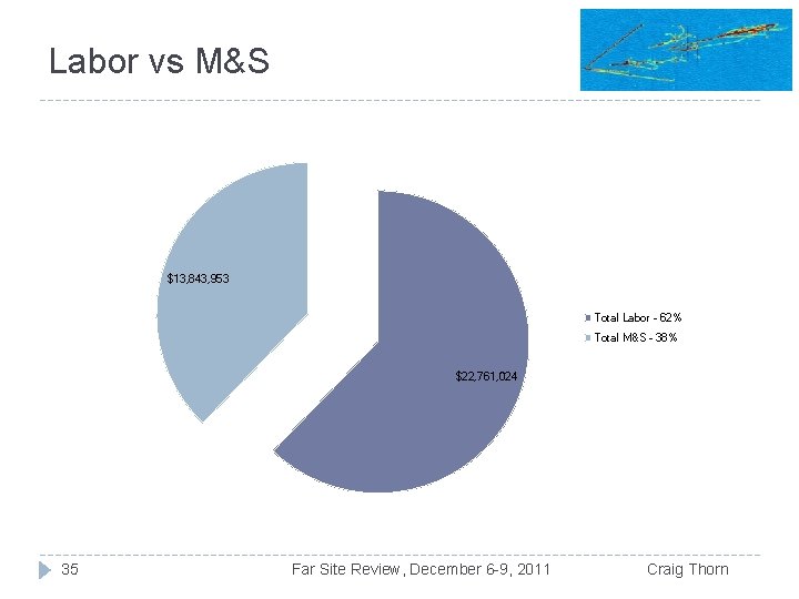
Labor vs M&S $13, 843, 953 Total Labor - 62% Total M&S - 38% $22, 761, 024 35 Far Site Review, December 6 -9, 2011 Craig Thorn
- Slides: 35