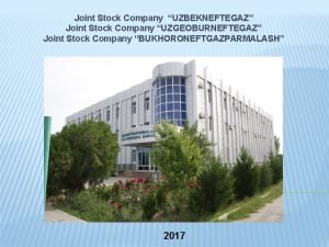
Joint Stock Company State Scientific Center Research Institute


- Slides: 30

Joint Stock Company «State Scientific Center - Research Institute of Atomic Reactors» KEY RESULTS OF POST-IRRADIATION EXAMINATIONS PERFORMED AT JSC “SSC RIAR” IN 2014 -2018 © Zvir E. A. , Zhitelev V. A. , Zakharov A. V. , Kryukov F. N. , Shishin V. Yu. , 2019 The 11 th Conference on Reactor Materials Science dedicated to the 55 th Anniversary of the SSC RIAR’s Reactor Materials Testing Complex Dimitrovgrad, JSC “SSC RIAR”, May 27 -31, 2019

INTRODUCTION JSC “SSC RIAR” operates the largest Russia’s Reactor Materials Testing Complex capable of solving a wide range of tasks on examining materials and items from miniature electron-microscopic samples irradiated in research reactors to fuel assemblies after their operation in any of the existing types of nuclear reactors. The majority of examinations performed for the past five years was aimed at obtaining experimental data necessary to substantiate the performance of materials and components existing of and cores designed of various reactors. 2

RESEARCH IN PROPULSION REACTORS RIAR has always played an important role in the creation and improvement of cores for propulsion reactors: floating reactors, atomic icebreakers, low-power plants, being the key expert in the experimental justification of the proposed versions of items and materials. Work on propulsion reactors began in March 1964, when the fuel assembly from the world's first atomic icebreaker "Lenin" arrived for research. 3

KEY PARAMETERS OF SFAS EXAMINED UNDER PROPULSION REACTORS TOPIC Year Fas, components 2014 SFA from icebreaker “Vaygach” 2014 -2015 2014 -2017 2018 2014 2013 -2014 Effective full power hours/ burnup > 40000 h / 1, 1 g f. f. /cm 3 LFA SNPP-3, fuel rods with ~ 9000 h / claddings from alloy 42 ХНМ 0, 38 g f. f. /cm 3 LFA, fuel rods with claddings ~ 15000 h / from alloy 42 ХНМ 0, 95 g f. f. /cm 3 FA “Harland” Units 6 and 8, fuel ~ 29000 h / rods with claddings from alloy 0, 9 g f. f. /cm 3 42 ХНМ of different thickness ~ 5900 h / 0, 3 g f. f. /cm 3 LFAs, fuel rods with claddings ~ 30000 h / from alloy 42 ХНМ 0, 7 -1, 0 g f. f. /cm 3 LFA 14 -14, fuel rods with ~ 23000 h / claddings from alloy E 110 after 1, 0 g f. f. /cm 3 re-irradiation FA “Harland” Unit 7 , fuel rods ~ 24000 h / with claddings from alloys E 110 0, 82 g f. f. /cm 3 and E 635, E 635 М Tasks Justify Gen IV cores Justify core designs for new-gen icebreaker with reactor RITM-200, SNPPs, floating reactors and Navy Gen-V facilities Confirm reliability and lifetime of items of the fist of a kind power unit of floating NPP with a KLT-40 S reactor “Mikhail Lomonosov» Select promising cladding design and material option 4

SFA FROM ICEBREAKER “VAYGACH” Fuel rod cross-section Fuel rod micro-structure - - 0, 2 b. В - - р р - - o о 02 -- 1000 Fuel rod 25 800 20 600 15 400 10 200 5 0 0 0 FA 30 200 400 600 Test temperature, С u, t, % 1200 YS, UTS, МPа Pin-type fuel rods with dispersed fuel kernel based on uranium intermetallic with cladding from chromium-nickel alloy 42 XHM showed high performance and operational reserve to improve the newgeneration cores. 800 Mechanical properties of alloy 42 ХНМ vs. temperature (Т irr. = 300°С; neutron fluence 2· 1026 n/m 2) 5

FUEL RODS FROM LOOP FA 14 -14 AFTER RE-IRRADIATION Task – get experimental data on the fuel rods performance under high burnups to improve the core of high-energy efficient reactor KLT-40 C (first of the kind unit). Performance achieved: effective full power hours ~ 23000 h; burnup - 1, 0 g f. f. /cm 3. q All re-irradiated fuel rods preserved their integrity, shape and dimensions. q No defects showing performance failure were revealed. Fuel rod fragments Fuel rod cladding Fuel composition 6

THERMAL TESTS OF FUEL RODS WITH CLADDINGS 42 ХНМ Task - get experimental data on the behavior of dispersed fuel rods with claddings from alloy 42 ХНМ at a temperature exceeding the operational one to define the performance limits for cladding material and fuel rods of this type. Thermal tests and PIEs were performed for 29 irradiated fuel rods of different design with dispersed fuel and cross-shape cladding from alloy 42 ХНМ. Fuel rods with cermet fuel (uranium dioxide granules in silumin) showed their high resistance to leakage as compared to standard fuel (intermetallic grit in silumin) under the same conditions (burnup, design, heating rate). 120 mm from the 40 mm from the bottom a b Appearance (a) and microstructure (b) of a fuel rod with standard fuel, burnup ~ 0, 3 g • f. f. /cm 3, cladding thickness 0, 30 mm after thermal tests at 625 °С. 7

VVER-1000 PIEs Tasks: q Examine the state of FA, fuel rods, skeleton components after operation; q Confirm designed performance characteristics and justify the operational reliability and safety of improved fuel; q Confirm characteristics of new materials applied; q Define causes and mechanism of fuel rod leakage. In 2014 -2018 we examined 11 FAs spent at Kalinin, Balakovo and Rostov NPPs, of which eight were TVSA of different modifications and three were TVS-2 M. In 2018, we started examining FA TVS-2 M from Balakovo NPP that contains 18 experimental fuel rods with claddings from new alloys E 110 M, E 635 M and E 125. TVSA TVS-2 M 8

CHARACTERISTICS OF EXAMINED FAs VVER-1000 № FA NPP Fuel campaigns / Burnup, operation period. , MW day/kg. U EFPD Cladding material Pellet size Dн/Dch 1 TVSA № 1 2 / 613, 6 31, 27 2 TVSA-PLUS № 1 Kalinin 2 / 973, 7 40, 07 3 TVSA-PLUS № 2 2 / 973, 7 43, 91 4 TVA-ALFA № 1 2 / 671, 9 32, 87 5 TVA-ALFA № 2 3 / 942, 5 40, 87 6 TVA-ALFA № 3 4/1255, 6 55, 00 7 TVA-ALFA № 4 5 / 1574, 2 57, 60 E 110 opt. electrolyt. 8 TVSA-5 М № 1 5 / 1540, 32 59, 37 E 110 sponge 18 fuel rods - 7, 8/0 Э 110 7, 6/1, 2 Kalinin 9 TVS-2 М № 1 Balakovo 1 / 482, 7 24, 36 10 TVS-2 М № 2 Rostov 2 / 959, 6 40, 96 11 TVS-2 М № 3 Balakovo 3 / 1447, 4 51, 17 7, 57/1, 4 E 110 opt. sponge 7, 6/1, 2 7, 8/0 9

Creep strain at cladding-to-fuel contact 0. 8 0. 7 0. 6 0. 5 0. 4 0. 3 0. 2 0. 1 0. 0 25 35 45 55 Burnup, MW·day/kg. U 65 Fuel rods sketches 75 Fuel rod elongation 25 Elongation, mm Strain, % DEFORMATION OF FUEL RODS WITH E 110 CLADDINGS 20 15 10 5 0 0 10 20 30 40 50 Burnup, MW·day/kg. U 60 70 Standard cladding, pellet 7, 57/7, 6 mm Thinned cladding, pellet 7, 8 mm 10

COMPARISON OF E 110 AND E 110 opt. CLADDINGS Strain, % Creep strain of E 110 and E 110 opt. When contacting with fuel 0. 8 0. 7 0. 6 0. 5 0. 4 0. 3 0. 2 0. 1 0. 0 Claddings E 110 opt. are characterized by higher thermal creep resistance and have better strength properties 45 50 55 60 Average burnup, MW day/kg. U E 110 opt. E 110 65 700 650 600 a 550 500 45 50 55 60 Average burnup, MW·day/kg. U 65 Ultimate strength, MPa Ultimate strength of alloys E 110 and E 110 opt. Obtained during testing of ring samples from claddings with different burnups at 20°С (a) and 380°С (b) 450 400 350 b 300 250 45 50 55 60 Average burnup, MW·day/kg. U 65 11

EXAMINED LEAKY FUEL RODS VVER-1000 Burnup, MW day/kg. U ADF Cause of leakage Location of a primary defect 1 TVSA № 1 31, 27 no Debris damage Under AVG 2 TVSA-PLUS № 1 Kalinin 40, 07 yes Debris damage Under AVG 3 TVSA-PLUS № 2 43, 91 yes Debris damage Under AVG № FA NPP 4 TVS-2 М № 1 Balakovo 24, 36 no Debris damage Under SG 12 5 TVS-2 М № 2 Rostov 40, 96 no Debris damage Under SG 1 ADF – anti-debris filter; AVG – anti-vibration grid; SG – spacer grid 12

INTERACTION WITH ALIEN ITEMS (DEBRIS-DAMAGE) Primary defects TVSA № 1 TVSA-PLUS № 2 Macro-structure in fuel rod cross-section at the debris-damage location 13

FA COMPONENTS DAMAGED WITH ALIEN ITEMS FROM LEAKY FUEL RODS Cladding partthrough defect Damage of AVF cell walls Abrasion of guide tube tip Elementary analysis of alien items revealed on ADF showed that the majority of them were bent plates from steel Х 18 Н 10 Т coated with crust 14

SECONDARY DEFECTS OF LEAKY FUEL ROD CLADDINGS External appearance of leaky VVER fuel rods: q spiral-like lite strap on the gas plenum; q change of color and deformation of claddings in some spots; q сracks in claddings; q crystallization of fission products on the cladding surface at the places of through-the-thickness cracks. TVSA-PLUS № 1 TVSA № 1 Gad plenum Between SG 12 and SG 13 TVSA-PLUS № 2 15

MICROSTRUCTURE OF TVSA-PLUS № 2 LEAKY FUEL ROD CLADDING At debris-damage Middle Bottom Gas plenum H content in the leaky fuel rod cladding H content, % Fuel column upper part 0. 35 0. 3 0. 25 0. 2 0. 15 0. 1 0. 05 0 Bulk hydrides 0 1000 2000 3000 Coordinate, mm 4000 16

PIEs OF CONTROL ROD ABSORBERS Examined for the first time: - Two control rod absorbers (design 2173. 000) with powder combined kernel (dysprosium titanate + boron carbide) and cladding from alloy 42 ХНМ, spent for 10 calendar years in reactor VVER-1000, 1 st Unit, Kalinin NPP. В 4 С Dy 2 Ti. O 5 а б - One control rod absorber (design 2755. 000) with pellet combined kernel (dysprosium titanate + boron carbide) and cladding from alloy 42 ХНМ, spent for 2, 5 years as emergency rod at Balakovo NPP, 4 th Unit. Absorbers VVER-1000 control rod absorber 2173. 000 (a) and 2755. 000 (b) 17

PIEs OF CONTROL ROD ABSORBERS Task – examine state of fuel rods of both designs after operation in reactor, confirm their designed lifetime and assess a possibility of its extension. a b Fuel rod surface X-ray pattern of fuel rod sections Typical microstructure of absorber cladding (a) and welds of power end components (b) 18

PIEs OF CONTROL ROD ABSORBERS The state of absorber claddings, welded joints, absorbing kernels, both powder and pellet, as well as the high plastic properties of cladding material from alloy 42 ХНМ indicate that they not only preserved their performance characteristics after operation in the reactor, but also have long residual lifetime. Examination results used for: q Extending up to 15 years the designed lifetime of absorbers 2173. 000 with combined powder absorbing kernels. The PIEs results and recommendations on the extension of control rod absorber designed lifetime confirm the practicability and high significance of regular examinations. 19

KEY CHARACTERISTICS AND IRRADIATION PARAMETERS OF EXPERIMENTAL FUEL PINS IN BN-600 Parameter KEFA-1 KEFA-6 KEFA-7 KEFA-2 EFA-4 KEFA-3 EFA-5 Fuel rod type BN-600 BN-1200 BREST Fuel rod nominal length, mm 2400 2075 2050 Fuel column nominal height, мм 1030 850 1100 Cladding materials Ch. S 68 -ID CW EF 164 -ID CW EP 823 -Sh Cladding diameter/ thickness, mm 6, 9 / 0, 4 9, 3 / 0, 6 9, 7 / 0, 5 Fuel rod max linear power, k. W/m 38, 3 39, 3 38, 3 44, 2 47, 3 37, 4 39, 9 Max burnup, % h. a. 5, 5 3, 9 7, 5 5, 1 5, 0 4, 5 3, 8 Max damage dose, dpa 55 37 74 62 59 53 48 20

STATE OF FUEL RODS IN THE EXAMINED FAs Count rate, pulse/s All FAs retained their integrity and original shape; no defects in their structural components were revealed as well as no damage to fuel rods during irradiation or transport-technological operations. Typical fuel rod top 400 350 300 250 200 150 100 50 0 800 1000 1200 1400 1600 1800 2000 2200 Coordinate from fuel rod bottom, mm - Cs-137 Fuel rods attachment area - Ru-106 - Cs-134 - Mn-54 Fuel rods in all fuel assemblies show the FP distribution corresponding to the neutron flux axial distribution and indicate the uniform-inheight distribution of the main fissile component plutonium-239, and the absence of fuel overheating. 21

STATE OF FUEL RODS IN THE EXAMINED FAs q Results of cladding puncturing and analysis of amount and content of gas phase confirmed the fuel rods to be leak tight. 400 Change in diameter, % Volume of fission gas in the gas plenum, cm 3 q Feature of SNUP fuel rods is less FGR from fuel and increase of cladding diameter as compared to rods with oxide fuel. UO 300 200 100 (U, Pu)N 1. 6 UO 2 1. 2 0. 8 0. 4 (U, Pu)N 0 800 0 200 300 400 500 600 1300 1800 Distance from the lower part of FR, mm Irradiation time, FPD FGR in KEFAs-1, 6 and 7 fuel rods Averaged data on change in diameter of KEFA-7 fuel rods 22

SNUP FUEL SWELLING AND INTERACTION WITH CLADDING Averaged data on KEFA-7 fuel rods SNUP fuel microstructure Fuel-to cladding gap Gap size, m 60 50 40 30 20 10 Burnup 5, 5 % h. a. Burnup 7, 5 % h. a. q Fuel-to-cladding gap in thin (6, 9 mm) and thick (9, 3 -9, 7 mm) fuel rod was up to burnups 7, 5 and 5, 0 %h. a. , respectively. In some cross-sections the gap size ranges from 0 to 20 m in different diametric dimensions. q Max rate of SNUP fuel free swelling (depending on burnup) in the cross-sections near the CMP in fuel rods with helium substrate was 1, 6… 2, 4 per 1 % h. a. 0 0 200 400 600 800 1000 Distance from the fuel column bottom, mm Swelling, % Before irradiation SNUP fuel swelling 14 12 10 8 6 4 2 0 0 200 400 600 800 1000 Distance from the fuel column bottom, mm - in plane geometry; - in density. 23

CORROSION STATE OF SNUP CLADDINGS Typical corrosion in nitride fuel claddings is local; corrosion products - oxides of steels metal components. Mass fraction of oxygen in the fuel is less than 0. 1%, the depth of corrosion did not exceed 60 microns. Corrosion of cladding EK 164 -ID CW (fuel rod EFA-4): SEM pattern of a cross-section fragment and elements distribution map in corrosion area 24

PECULIAR FEATURES OF MICROSTRUCTURE AND ELEMENTARY COMPOSITION OF NITRIDE FUEL CLADDINGS FROM AUSTENITIC STEELS Carbon content, rel. unit 7 70 6 60 5 50 4 40 3 30 2 20 1 10 0 0 Iron content, rel. unit Increased carbon content from the inside surface Increased etching at the grain boundaries from the inside surface of cladding from steel Ch. S 68 -ID 0 100 200 300 400 Distance from the cladding outside surface, m - C - Fe 25

PECULIAR STATE OF GRAIN BOUNDARIES IN STEELS Ch. S 68 AND EK 164 Oxide fuel rod cladding Nitride fuel rod cladding 1. Microstructure of the outside surface of nitride fuel rod cladding was peculiar in a significantly higher content of phase М 23 С 6 at grain boundaries. 2. A source of carbon inside the fuel rod can be an impurity of carbon in nitride fuel. I. Carbon, as well as nitrogen, intensifies the effect of high-temperature irradiation-induced embrittlement of austenitic steel. II. A layer of large grain-boundary carbonitride precipitates weaken the grain boundaries. 26

FRACTOGRAPHY OF DAMAGE SURFACE OF AUSTENITIC STEEL CLADDING SAMPLES AFTER MECHANICAL TESTS SNUP fuel rod cladding Oxide fuel rod cladding Outside Inside A zone of brittle inter-crystalline fracture was revealed on the cladding inside surface 27

MECHANICAL TESTS RESULTS FOR SNUP FUEL ROD CLADDINGS KEFA-3 EFA-4 KEFA-7 (EP 823 -Sh; 4, 5 % т. а. ; 53 сна. (Ch. S 68 -ID CW; 7, 5 % h. a. ; 74 dpa, (EK 164 -ID CW; 5, 0 % h. a. ; 59 dpa. Mass fraction of carbon in fuel 0, 14%) Mass fraction of carbon in fuel 0, 07%) Mass fraction of carbon in fuel 0, 14%) Average ultimate strength and total relative elongation values over FAs obtained when testing longitudinal segment samples at temperatures corresponding to the operational ones. 28

CONCLUSION Tasks of Reactor Materials Testing Complex for 2019 -2023 годы: q Implementation of scheduled research activities. q Maintaining the Complex’s position in the research market in the main areas of activity. q Expansion of the Complex’s capabilities for solving complicated tasks on examining properties and characteristics of irradiated materials and items. q Development of the experimental base, further improvement of research equipment, development and introduction of new research methods. 29

THANK YOU FOR ATTENTION!
 Joint stock company age of exploration
 Merits and demerits of joint stock company
 Ssush1 compare and contrast
 Stock company definition
 Frt tes psikologi
 Importance of joint stock company
 Jointstock company
 Tdt investment and development jsc
 National research center kurchatov institute
 National research center kurchatov institute
 National center for scientific research demokritos
 Development research centre of the state council
 Features of preferred stock
 Stock sauce
 Common stock characteristics
 Stock initial
 Phuong nam garment joint stock
 Case bank
 Lamb grading chart
 Membrana tectoria
 Example of semi-permanent joint is______
 Joint venture account
 Break joint vs spool joint
 Fibrous joints
 Scientific inquiry vs scientific method
 How is a scientific law different from a scientific theory?
 Company analysis and stock valuation
 Company analysis stock valuation
 Stock verification definition
 Limited company vs partnership
 Winding up of a company
