IPv 4 to IPv 6 Network Address Translation


---Indicates the")

 4 4 4 172.")


 · PAT does not work with H. 323 applications,")


 4 IP version 6 (IPv 6) is a new")


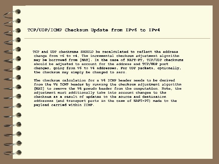
 NAT-PT offers a straight forward solution")


- Slides: 29
IPv 4 to IPv 6 Network Address Translation
Introduction 4 What is the current internet addressing scheme and what limitations does it face. 4 A new addressing scheme that would resolve the limitations, and an interim path towards the new scheme.
What we will cover during this presentation : 4 IPv 4 Address structure 4 The IPv 4 address resource problem 4 Network Address translation of private address to global addresses for IPv 4 4 4 address conservation. IPv 6 Specifications (rfc 1883) IPv 6 addressing structure (rfc 1884) IPv 4 to IPv 6 transition and NAT considerations IPv 6 to IPv 4 address translation at the edge router and higher layer consideration. Need for port number translations in IPv 4 to IPv 6 NAT(rfc 2766)
IPv 4 Address Scheme : – IP Packet Format 4 An IP packet contains several types of information, as illustrated. 4
4 Version---Indicates the version of IP currently used. · IP Header Length (IHL)---Indicates the datagram header length in 32 -bit words. · Type-of-Service---Assigns datagrams various levels of importance. · Total Length---Specifies the length, in bytes, of the entire IP packet. · Identification---Contains an integer that identifies the current datagram. · Flags---The two low-order (least-significant) bits control fragmentation. The low-order bit specifies whether the packet can be fragmented. The middle bit specifies whether the packet is the last fragment in a series of fragmented packets. The third or high-order bit is not used. · Fragment Offset---Indicates the position of the fragment's data relative to the beginning of the data in the original datagram. · Time-to-Live---Maintains a counter that gradually decrements down to zero, at which point the datagram is discarded. This keeps packets from looping endlessly. · Protocol---Indicates which upper-layer protocol receives incoming packets after IP processing is complete. · Header Checksum---Helps ensure IP header integrity. · Source Address---Specifies the sending node. · Destination Address---Specifies the receiving node. · Options---Allows IP to support various options, such as security. · Data---Contains upper-layer information.
IPv 4 Addressing 4 As with any other network-layer protocol, the IP addressing scheme is integral to the process of routing IP datagrams through an internetwork. Each IP address has specific components and follows a basic format. These IP addresses can be subdivided and used to create addresses for subnetworks, as discussed in more detail later. 4 Each host on a TCP/IP network is assigned a unique 32 -bit logical address that is divided into two main parts: the network number and the host number. The network number identifies a network and must be assigned by the Internet Network Information Center (Inter. NIC) if the network is to be part of the Internet. An Internet Service Provider (ISP) can obtain blocks of network addresses from the Inter. NIC and can itself assign address space as necessary. The host number identifies a host on a network and is assigned by the local network administrator. 4 The 32 -bit IP address is grouped eight bits at a time, separated by dots, and represented in decimal format (known as dotted decimal notation). Each bit in the octet has a binary weight (128, 64, 32, 16, 8, 4, 2, 1). The minimum value for an octet is 0, and the maximum value for an octet is 255. The figure below illustrates the basic format of an IP address. 4
Private addresses to assign within a network (Not globally routable) 4 4 4 172. 16. 0. 0/255. 0. 0 192. 168. 0. 0/255. 0 10. 0/255. 0. 0. 0 So in order to resolve the shortage of IPv 4 addresses so far the solution has been Network Address Translation as follows. With the following scheme a network can have almost infinite IP addresses yet never contribute to the finite globally routable IP addresses shortage. In its simplest configuration, the Network Address Translator (NAT) operates on a router connecting two networks together; one of these networks (designated as inside) is addressed with either private or obsolete addresses that need to be converted into legal addresses before packets are forwarded onto the other network (designated as outside). The translation operates in conjunction with routing, so that NAT can simply be enabled on an Internet access router when translation is desired. 4 Use of a NAT device provides RFC 1631 -style network address translation on the router platform. The goal of NAT is to provide functionality as if the private network had globally unique addresses and the NAT device was not present.
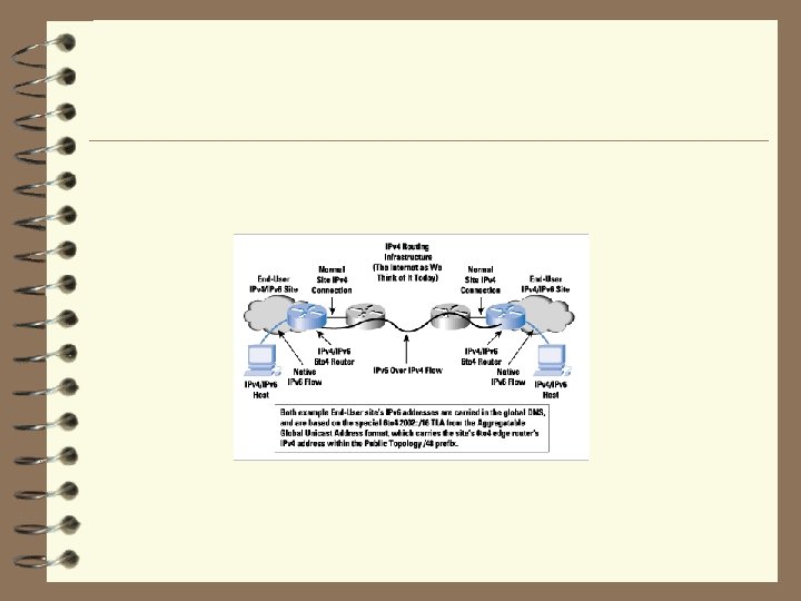
Schema diagram:
4 The above method is useful yet lacks a viable solution to globally routable IP address problem. Since for every private IP address a globally routable IP address is needed for direct translation. Well in most cases it is not very profitable or at all possible to contain many IP addresses. 4 Dynamic Network address translation: One way to resolve this issue would be through Port Address Translation (PAT) as follows:
– PAT (Port Address Translation) · PAT does not work with H. 323 applications, multimedia applications, and caching nameservers. · PAT works with DNS, FTP and passive FTP, HTTP, mail, RPC, rshell, Telnet, URL filtering, and outbound traceroute. · Finally when we have completely exhausted all available IPv 4 resources we need to explore the new version of Ipng
NAT Enroute to translate Host-A NAT router --------<Outer IP header, with src=Addr-A, Dest=Addr-X>, embedding <End-to-end packet, with src=Addr-k, Dest=Addr-X> ---------------> Host-X ------ <Outer IP header, with src=Addr-k, Dest=Addr-X>, embedding <End-to-end packet, with src=Addr-k, Dest=Addr-X> --------------> <Outer IP header, with src =Addr-X, Dest=Addr-k>, embedding <End-to-end packet, with src =Addr-X, Dest=Addr-k> <-----------------
NAPT router enroute to translate: Host-A ------ NAPT router ------ Host-X ------ <Outer TCP/UDP packet, with src=Addr-A, Src Port=T-Na, Dest=Addr-X>, embedding <End-to-end packet, with src=Addr-Nx, Src Port=T-Nx, Dest=Addr-X> ---------------> <Outer TCP/UDP packet, with src=Addr-Nx, Src Port=T-Nxa, Dest=Addr-X>, embedding <End-to-end packet, with src=Addr-Nx, Src Port=T-Nx, Dest=Addr-X> --------------------> <Outer TCP/UDP packet with src=Addr-X, Dest=Addr-Nx, Dest Port=T-Nxa>, embedding <End-to-end packet, with src=Addr-X, Dest=Addr-Nx, Dest Port=T-Nx> <-----------------
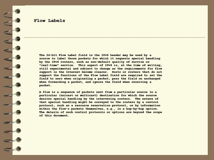
IPv 6 Specification (rfc 1883) 4 IP version 6 (IPv 6) is a new version of the Internet Protocol, designed as a successor to IP version 4 (IPv 4) [RFC-791]. The changes from IPv 4 to IPv 6 fall primarily into the following categories: 4 Expanded Addressing Capabilities IPv 6 increases the IP address size from 32 bits to 128 bits, to support more levels of addressing hierarchy, a much greater number of addressable nodes, and simpler autoconfiguration of addresses. 4 The scalability of multicast routing is improved by adding a "scope" field to multicast addresses. 4 And a new type of address called an "anycast address" is defined, used to send a packet to any one of a group of nodes. 4 Header Format Simplification Some IPv 4 header fields have been dropped or made optional, to reduce the common-case processing cost of packet handling and to limit the bandwidth cost of the IPv 6 header. 4 Improved Support for Extensions and Options Changes in the way IP header options are encoded allows for more efficient forwarding, less stringent limits on the length of options, and greater flexibility for introducing new options in the future. 4 Flow Labeling Capability A new capability is added to enable the labeling of packets belonging to particular traffic "flows" for which the sender requests special handling, such as non-default quality of service or "real-time" service. 4 Authentication and Privacy Capabilities Extensions to support authentication, data integrity, and (optional) data confidentiality are specified for IPv 6.
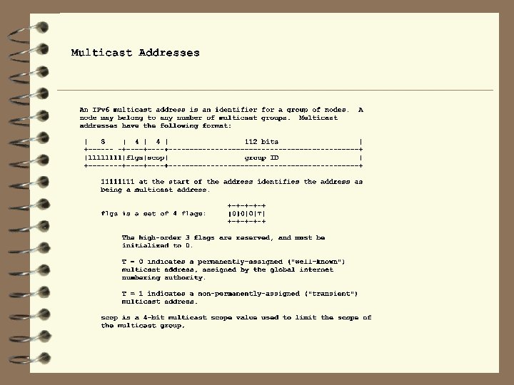
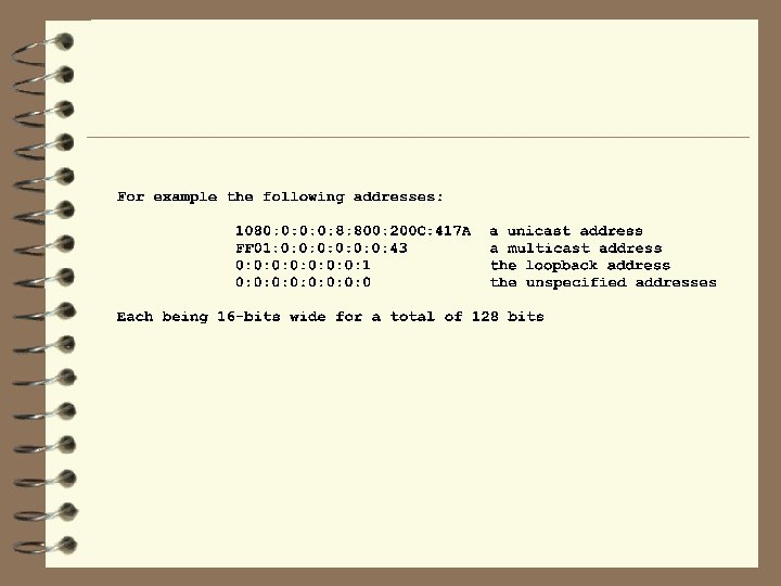
4 IPv 6 Addressing scheme overview 4 IPv 6 addresses are 128 -bit identifiers for interfaces and sets of interfaces. There are three types of addresses: 4 Unicast: An identifier for a single interface. A packet sent to a unicast address is delivered to the interface identified by that address. 4 Anycast: An identifier for a set of interfaces (typically belonging to different nodes). A packet sent to an anycast address is delivered to one of the interfaces identified by that address (the "nearest" one, according to the routing protocols' measure of distance). 4 Multicast: An identifier for a set of interfaces (typically belonging to different nodes). A packet sent to a multicast address is delivered to all interfaces identified by that address. 4 There are no broadcast addresses in IPv 6, their function being superseded by multicast addresses.
4 An example of a Unicast address format which will likely be common on LANs and other environments where IEEE 802 MAC addresses are available is: | n bits | 80 -n bits | 48 bits | +----------------+----------------+ | subscriber prefix | subnet ID | interface ID | +----------------+----------------+ Where the 48 -bit Interface ID is an IEEE-802 MAC address. The use of IEEE 802 MAC addresses as a interface ID is expected to be very common in environments where nodes have an IEEE 802 MAC address. In other environments, where IEEE 802 MAC addresses are not available, other types of link layer addresses can be used, such as E. 164 addresses, for the interface ID.
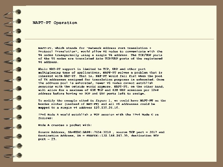
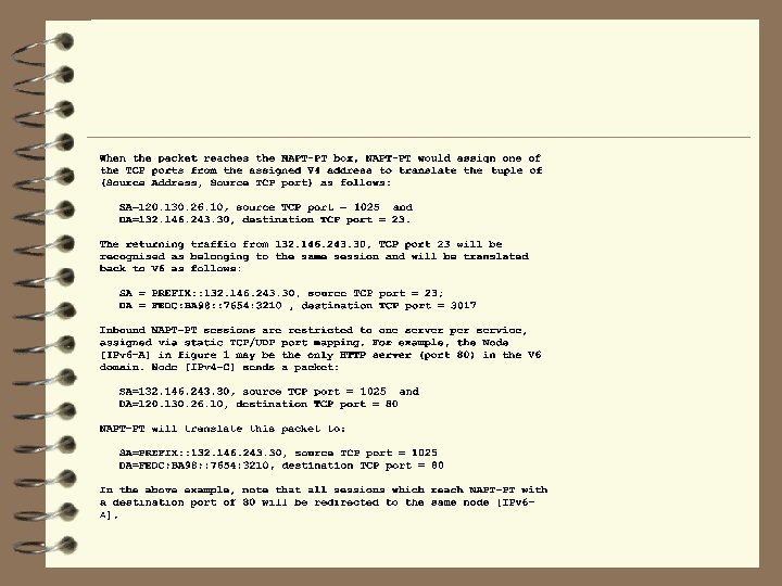
4 Traditional-NAT-PT Operation (V 6 to V 4) NAT-PT offers a straight forward solution based on transparent routing [NAT-TERM] and address/protocol translation, allowing a large number of applications in V 6 and V 4 realms to inter-operate without requiring any changes to these applications. In the following paragraphs we describe the operation of traditional-NAT-PT and the way that connections can be initiated from a host in IPv 6 domain to a host in IPv 4 domain through a traditional-NAT-PT 4 Basic-NAT-PT Operation [IPv 6 -B]-+ | +=======+ [IPv 6 -A]-+-[NAT-PT]-----| IPv 4 network |--[IPv 4 -C] | +=======+ (pool of v 4 addresses) Figure 1: IPv 6 to IPv 4 communication Node IPv 6 -A has an IPv 6 address -> FEDC: BA 98: : 7654: 3210 Node IPv 6 -B has an IPv 6 address -> FEDC: BA 98: : 7654: 3211 Node IPv 4 -C has an IPv 4 address -> 132. 146. 243. 30 NAT-PT has a pool of addresses including the IPv 4 subnet 120. 130. 26/24
The V 4 addresses in the address pool could be allocated one-to-one to the V 6 addresses of the V 6 end nodes in which case one needs as many V 4 addresses as V 6 end points. In this document we assume that the V 6 network has less V 4 addresses than V 6 end nodes and thus dynamic address allocation is required for at least some of them. Say the IPv 6 Node A wants to communicate with the IPv 4 Node C. A creates a packet with: Node Source Address, SA=FEDC: BA 98: : 7654: 3210 and Destination Address, DA = PREFIX: : 132. 146. 243. 30 NOTE: The prefix PREFIX: : /96 is advertised in the stub domain by the NAT-PT, and packets addressed to this PREFIX will be routed to the NAT-PT. The pre-configured PREFIX only needs to be routable within the IPv 6 stub domain and as such it can be any routable prefix that the network administrator chooses. The packet is routed via the NAT-PT gateway, where it is translated to IPv 4.
Close 4 Even with 20 years of TCP networks UUCP still exists 4 IPv 6 to IPv 4 NAT is just an iterim solution, will not work with all protocols. 4 Yet as a knowledgeable network professional we need to know about IPv 6 issues.