ADDRESS TRANSLATION MECHANISM OF 80386 Unit 2 PROTECTED


 Address Segmentation Unit Linear Address")


Bit: indicates if the entry can be used in address")
 bit: It is set before a write operation")


 x 4 Binar 00 0000 1100 y x 0100 ______ __")
 00010 H + DIR*4 = Index to PDE = 00010030")


 x 4 Binar 00 0001 0000 y x 0100 ______ __ 00")
 05001 H + Table*4 = Index to PTE (12 -bit) +")


 03000 H + Offset = Physical Address (12 -bit) + 08")

 • Performance degrades if the processor access two levels of tables")
")
 • TLB has 4 sets of eight entries each. • Each")

 • It automatically keeps the most commonly used Page Table Entries.")


- Slides: 49
ADDRESS TRANSLATION MECHANISM OF 80386 Unit 2
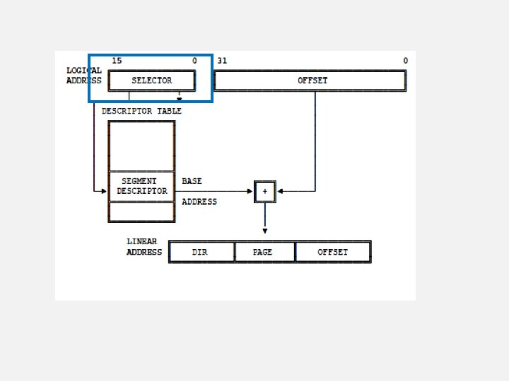
PROTECTED MODE ADDRESSING MECHANISM • 80386 transforms logical addresses into physical address two steps: • Segment translation: a logical address is converted to a linear address. • Page translation: a linear address is converted to a physical address. (optional) • These translations are performed in a way that is not visible to applications programmers.
• The following figure illustrates the two translations:
SEGMENTATION
Logical(Virtual) Address Segmentation Unit Linear Address
Base Address in LDTR Register Base Address in GDTR Register
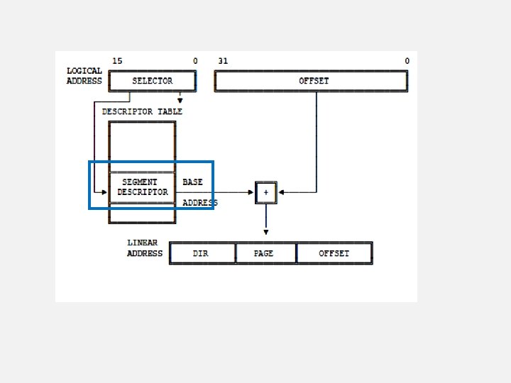
SEGMENT DESCRIPTOR
FOR CURRENTLY EXECUTING TASK
FOR EACH TASK
PAGING
SECOND PHASE Linear Address Paging Unit Physical Address
PAGE TRANSLATION • Mandatory if: Virtual 8086 Page protection Page virtual memory • E. g: LA 4 GB mapped to 16 MB PA • Total Pages= 1, 048, 496 pages in PA • Page size= 4096 bytes
SEGMENTATION VS PAGING Sr. No Segmantation Paging 1 PA Organized as Segments PA Organized as Page 2 Size is Variable Size is Fix 3 1 byte to 4 GB 4 KB 4 More efficient use of memory Less efficient use of memory 5 Less Fragmentation More Fragmentation 6 Implementation of memory management software is not simplified Implementation of memory management software is simplified
PAGE FRAME • A page frame is a 4 K-byte unit of contiguous addresses of physical memory. • Pages begin onebyte boundaries and are fixed in size.
COMPONENTS OF PAGING MECHANISM • Page Directory • Page tables • Page frame Tabl e Form 32 bit descriptors Total 1024 descriptors 4 KB long
LINEAR TO PHYSICAL ADDRESS TRANSLATION
PAGE DESCRIPTOR BASE REGISTER • CR 2 is used to store the 32 -bit linear address of page fault. • CR 3 (Page Directory Physical Base Address Register) stores the physical starting address of Page Directory.
PAGE DESCRIPTOR BASE REGISTER • The lower 12 bits of CR 3 are always zero to ensure that the Page Directory is always page aligned • A move operation to CR 3 automatically loads the Page Table Entry caches and a task switch through a TSS changes the value of CR 0. • MOV CR 3, EAX
PAGE DIRECTORY • PDE: -It is at the most 4 KB in size and allows upto 1024 entries are allowed. • The upper 10 bits of the linear address are used as an index to corresponding page directory entry • Page directory entry points to page tables.
PAGE DIRECTORY ENTRY
PAGE TABLES • PTE: -Each Page Table is 4 KB and holds up to 1024 Page Table Entries. • PTEs contain the starting address of the page frame and statistical information about the page. • Upper 20 bit page frame address is concatenated with the lower 12 bits of the linear address to form the physical address. • Page tables can be shared between tasks and swapped to disks
PAGE TABLE ENTRY • P(Present)Bit: indicates if the entry can be used in address translation. P-bit of the currently executed page is always high. • A (Accessed) Bit: It is set before any access to the page.
PAGE TABLE ENTRY • D (Dirty) bit: It is set before a write operation to the page is carried out. The D bit is undefined for PDEs. • OS Reserved Bits: They are defined by the operating system software. • U/S (User/Supervisor)Bit and R/W (Read/Write) Bit: They are used to provide protection. They are decoded as
EXAMPLE Linear Address : 0301008 A 0000 0011 0000 1000 1010 Binary 00 0000 1100 00 0001 0000 1000 1010 Hex (10 bits) (12 bits) 00 C 010 08 A
EXAMPLE
Hex 00 C(DIR) x 4 Binar 00 0000 1100 y x 0100 ______ __ 00 0011 0000 030
CR 3 (20 -bit) 00010 H + DIR*4 = Index to PDE = 00010030 H (12 -bit) + 030 H
EXAMPLE
Page Directory Entry
Hex 010(TABLE) x 4 Binar 00 0001 0000 y x 0100 ______ __ 00 0100 0000 040
PTA (20 -bit) 05001 H + Table*4 = Index to PTE (12 -bit) + 040 H = 05001040 H
EXAMPLE
Page Table Entry
PFA (20 -bit) 03000 H + Offset = Physical Address (12 -bit) + 08 AH = 03000 08 AH
EXAMPLE
TRANSLATION LOOKASIDE BUFFER(TLB) • Performance degrades if the processor access two levels of tables for every memory reference. • To solve this problem, the Intel 386 DX keeps a cache of the most recently accessed pages and this cache is called Translation Lookaside Buffer (TLB). • TLB is a 4 way set associative 32 entry page table cache
TRANSLATION LOOKASIDE BUFFER(TLB)
TRANSLATION LOOKASIDE BUFFER(TLB) • TLB has 4 sets of eight entries each. • Each entry consists of a TAG and a DATA. • Tags are 24 bit wide. They contain 20 upper bits of linear address, a valid bit (Validation of Entry) and three attribute bits(D, U/S and R/W) • Data portion of each entry contains upper 20 bits of the Physical address.
TLB ENTRY V D U/S R/W Upper 20 bit Linear Address Upper 20 -bit Physical Address
TRANSLATION LOOKASIDE BUFFER(TLB) • It automatically keeps the most commonly used Page Table Entries. • 32 -entry TLB coupled with a 4 K page size results in the coverage of 128 KB of memory addresses.
PAGING OPERATION • The paging unit hardware receives a 32 -bit linear address from the segmentation unit. • The upper 20 linear address bits are compared with all 32 entries in the TLB to determine if there is a match. • If there is a match (i. e. a TLB hit), then the 32 -bit physical address is calculated and will be placed on the address bus.
PAGING OPERATION • If PTE entry is not in TLB, the 80386 DX will read the appropriate PDE Entry. • If P = 1 on PDE ( the page table is in memory), then the 80386 DX will read the appropriate PTE and set the Access bit. • If P = 1 on PTE ( the page is in memory), then the Intel 386 DX will update the Access and Dirty bits as needed and fetch the operand.
PAGING OPERATION • The upper 20 bits of the linear address read from the page table will be stored in the TLB for future accesses. • If P = 0 for either PDE or PTE, then the processor will generate a page fault exception • This exception is also generated when protection rules are violated and the CR 2 is loaded with the page fault address
Paging Operation Linear Address Upper 20 bits available in TLB N Y (Page is present in physical memory, set A and D(if needed)) N P=1 in PDE? Y N (Page Table is present in physical memory, set access bit) P=1 in PTE? Page Fault Exception Y (Page is present in physical memory but entry is not there Update TLB in TLB, set A and D(if needed) )
PAGING OPERATION
PAGING Page m . . Page 2 Page 1 Page 0 Hard Disk Each running program has its own page table Page n Pages that cannot fit in main memory are stored on the hard disk linear virtual address space of Program 2 The operating system uses page tables to map the pages in the linear virtual address space onto main memory linear virtual address space of Program 1 Main Memory The operating system swaps pages between memory and the hard disk As a program is running, the processor translates the linear virtual addresses onto real memory (called also physical) addresses