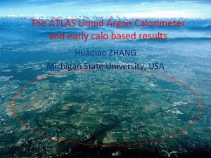
Installation and Commissioning of the ATLAS Liquid Argon


- Slides: 17

Installation and Commissioning of the ATLAS Liquid Argon Calorimeter Read-Out Electronics TWEPP 2008 Guy Perrot on behalf of the LAr Team 15 -19 September 2008

Introduction • ATLAS and the LAr Elements • The readout chain • Installation & Commissioning – System Generalities – Back-end Electronics – Front-end Electronics • Barrel • Endcaps – TTC distribution. • Noise in the detector. • Present status of the detector. 16 -09 -2008 Guy Perrot TWEPP 2008 2

ATLAS and the LAr Calorimeters Muon spectrometer: Air core toroids + muon chambers HEC Tracking: - Si pixels and strips - Transition radiation detector EMEC EMB FCAL Calorimetry : -EM: Pb-Liquid Argon (LAr) -HAD: Fe/scintillator, Cu/W-LAr The LAr calorimeters are hosted in 3 large cryostats. The barrel cryostat contains the Electromagnetic (EM) barrel. The endcap cryostats contain EM and Hadronic Endcaps and the Forward calorimeter. 16 -09 -2008 Guy Perrot TWEPP 2008 3

Readout Chain ROS • • • 5 elements in the chain: the Detector, the Front-End crate (FE), the Back-End crate (BE), The Read-Out. System PCs (ROS) and the Timing-Trigger and Control crate (TTC). TTC signals are transmitted from the TTC crate to both Front End (FE) and Back End (BE) crates. Calibration boards generate a pulse on the Electrode for calibration. The FE board amplifies, shapes and samples the signal from the electrode. Samples corresponding to a good event (Accepted by Level 1 trigger: L 1 A) are digitized and transmitted to the Read Out Driver (ROD) board in the BE crates. – Large dynamic range (10 Me. V to 3 Te. V): 3 gains per channel, 12 bit ADC, digitization at 5 MHz. – From 3 to 32 samples readout. 5 for Atlas Physics running. 32 used for many commissioning studies. The ROD board calculates Energy (also Time and Quality depending on energy level)) from these samples and transmits the information to the Read Out System (ROS). 16 -09 -2008 Back-end crate Guy Perrot TWEPP 2008 4

Installation & commissioning Some dates and numbers • • October 2004: Barrel cryostat in the cavern. • July 2005: First BE RODs installed in USA 15. • July 2005: First FE electronics installed on the Barrel. April 2006: All 3 cryostats in the cavern. Aug 2006: First cosmic signal recorded, Barrel (1 FE crate) with Tile calorimeter May 2007: Back End electronics completed. • Summer 2007: FE Low voltage power supplies fully available after refurbishment. April 2008: FE electronics refurbishment completed. 182468 Physics channels Detector Front End (FE) System • USA 15 TTC distribution System • • • Sept 2007: Endcap C Dec 2007: Endcap A May 2008: Readout of the full calorimeter, Closure of the apparatus. 16 -09 -2008 – – – 1524 Front End boards (FEBs) 58 Front End crates 58 LV power supply systems 115 High voltage modules Over 1600 fibers between FE and BE USA 15 Back End (BE) System – – – – – 192 ROD boards 16 ROD crates 68 ROS PCs Almost 800 fibers between RODs and ROSes 4 TTC crates 6 partitions in 3 crates and one controller crate 36 modules of 7 different types 8 optical couplers Over 200 fibers to FE and BE Guy Perrot TWEPP 2008 5

LArg Electronic Elements LV PS FE Crate Barrel side view with FE Crates & PS BE Read. Out Electronics 16 -09 -2008 USA 15 TTC Distribution LV 280 V Power Supplies HV Power Supplies Guy Perrot TWEPP 2008 6

Installation & commissioning • Procedure was to install hardware and test it as soon as possible in stand alone mode. Then to leave it running, integrate it, and use it whenever possible. • Electronic for the FE was installed one crate at a time with tests including pedestals and calibration runs using a specific acquisition system. • Electronic for the BE was also installed one crate at a time and tested with an injector system to replace the FE which was not yet connected. • As soon as these elements were tested and interconnected, they were integrated in the global acquisition system. • Detector has been commissioned continuously with the available readout system doing pedestal runs, calibration runs and cosmic runs to verify its behavior and stability. 16 -09 -2008 Guy Perrot TWEPP 2008 ch. 0, 4, 8, . . . , 60 (all calib. line #32) largerly distorted Damaged Calibration channel Examples of problem detected Dead FEB channel ch 94 dead Readout: almost flat wave 7

BE Installation & Commissioning • ROD installation & Commissioning Optical Splitters ROS PCs Injector System Half Crate under test ROD Commissioning system 6 injectors with 5 outputs and 30 2 to 1 Optical Splitter provides 60 FEBs inputs (half a ROD crate) 3 ROS PCs with 7 FILAR boards allow readout of 28 ROD outputs (half a ROD crate) TTC signals generated by the final TTC system Comparison of the injected data with the received data in the ROSes 16 -09 -2008 – Between August 05 and April 07, ROD crates have been filled and tested using the ROD commissioning system. – This system was also used to distributes signals to different ROD crates to develop online readout software. – Fibers between RODs and ROSes were commissioned between March 06 and June 07 when they were connected to the ROSes. • Final ROD commissioning with FEBs and ROSes + Event Builders. – Started in June 07 (1 st full ROD crate) and is still going on. Guy Perrot TWEPP 2008 8

Problem in the BE System • Could not run at high speed (40 KHz L 1 A). Doubling of the 1 m power cables – Oscillations on 3. 3 V due to current surge made the power supply trip. – Was only seen when we could exercise the crate at high speed with all FEB inputs and full parallel readout. • 3. 3 m. F Capacitor added on ROD Solved by doubling the power cables and adding a big capacitor on each ROD L 1 A 30 KHz 12 samples raw 1/100 evts after modifications L 1 A 30 KHz 10 samples raw 1/100 evts before modifications Diff voltage 3. 3 v and Return (AC coupled) Averaged on 1000 sweeps 50 m. V/square (measured on power supply ) Current averaged Current of 3. 3 V 10 A/square TBM Busy 100 Us/square 16 -09 -2008 200 Us/square Guy Perrot TWEPP 2008 9

FE Installation & commissioning FE Crate • FE Installation started on Barrel in summer 2005 and May and August 2006 for the Endcaps. – No cooling infrastructure available for the Barrel. – 2 LV power supply and 2 cables with 48 fibers between UX 15 and USA 15 moved around. • – One FEB read by one ROD then by LAL FEB test board for the Barrel (due to the absence of cooling). – Full BE read out of one FE crate using standard TDAQ software for the Endcaps (cooling with a stand alone system). First EM BE setup • EC BE setup • • • 16 -09 -2008 3 Different BE setups used for commissioning between summer 2005 and December 2006 Barrel FE was fully tested in summer 06 and Endcaps in December 06 but with only a few power supplies available. All power supplies were available in August 07 after refurbishment. Complete refurbishing of FE boards done between July 07 and March 2008 (Endcap C, A and Barrel sequentially). First readout of the full LAr detector in May 08. Guy Perrot TWEPP 2008 10

Why FE Boards Refurbishing ? • • • 16 -09 -2008 Initially: Missing voltage level adaptation on two signals between 5 V DMILL chips and 2. 5 V DSM chips. Risk of increasing failure for these components. Adaptation made with a serial resistor on the used signal and a pull-up on the other after cutting trace. Shaper constant changing after sometime. Fuses which had been burned during tests of the shaper chips for correct shape were getting reconnected. Cutting the pins corresponding to the burned fuses of each chip solves the problem. Corrosion on FE boards discovered during refurbishment. Was due to bad cleaning process after repair of part of the production. About 50 boards damaged beyond repair. Others recovered after new cleaning. A new batch of 40 boards is being produced for spares. Guy Perrot TWEPP 2008 11

FE LV Power Supplies • • FE Low voltage Power supplies have been plagued by failures. A task force was setup during summer 2006 and a deep review of the power supply was done. It led to many modifications and the replacement of many components in the design in order to be able to use these power supplies for the first years of LHC operation. All 58 needed power supplies have been refurbished between Spring and August 07. They are all operational though one is working without its redundancy. Meanwhile, a backup project has started with 2 companies to produce new designs and prototypes, since reliability of the refurbished supplies can’t be guaranteed for the lifetime of the LHC operations (as concluded by the review). – Design is being completed (Oct 2008) – Prototypes construction and evaluation (early 2009) – LAr will decide whether exercise the option of a new full production in the first half of 2009 • • In June 2008, when the Barrel toroid was turned on for the first time, it was observed that the induced magnetic field in some of the Endcaps LVPS was too high. It took 2 months to understand that the installed shielding was not wide enough, to produce new shielding plates and install them in very tight positions. 16 -09 -2008 Guy Perrot TWEPP 2008 12

TTC System commissioning • • Installation of the TTC system started in September 05. It was completed in November 05 (excluding LTPIs installed in May 08). It was first used for BE tests and its functionalities were progressively used and tested whenever they were needed. It was completely connected in August 07. Real problems were only discovered when we started to use the system at high speed in long term tests (Fall 07): How does it happen: Short glitch on the LTP output clock only happens with a VME access, a transition on the LTP internal orbit signal plus Internal LTP clock and external CTP clock having a different level. Zoom This is not the expected behavior of the component! – Occasional L 1 A getting through when the BUSY is present. • • Consequence is Phase shift between LTP Clk (NIM) and TTCex output Clk for a few ms until the TTCex locks again. Reason: Glitch (ns) on the Busy output of the ROD busy module due to VME accesses to its status. Cure: use the NIM output which filters that glitch instead of the OC TTL output. – A few corrupted events received from FEBs during long runs (hours or days) at high rate. • • Reason: Glitch on the clock output of the LTP module due to VME accesses to its status. Cure: new LTP firmware. Clk glitch at input of TTCex phase comparator stops it for 350 Us. Zoom of Clks FEB Data starts to be corrupted, then FEB QPLL unlocks for 400 ms Looks simple but took 6 months to understand! 16 -09 -2008 Guy Perrot TWEPP 2008 13

Noise Problems (1) • • • Noise correlated to the Tile Hadronic calorimeter power supplies have been observed with a frequency peak at 17 MHz on channels close to the heater cables inside the FEC pedestal. Corrected by adding more filtering on the heater cables in the pedestal and modifying the Tile LV power supplies. Noise bursts seen in cosmic runs and pedestal runs (in some events many cells many sigma above the noise). – – Odd. Cell. Monitoring tool is a very efficient tool to investigate this phenomenon. LVL 1 output with frequency analyzer very efficient complementary tool to characterize noise bursts. If perfect gaussian behavior: 55 (~27 k x 0. 2%) odd cells Almost exclusively affecting the Presampler. expected per event. Bursts with frequencies of 3. 5 MHz - 6 MHz, every 250µs Nice peak around 0. 3% but also noise bursts! 3. 5 MHz - 6 MHz peaks 16 -09 -2008 Guy Perrot TWEPP 2008 14

Noise Problems (2) • Investigations have shown that the noise was coming through the HV cables. • Cure is to add 1 m. F capacitors between HV outer shield and Cryostat GND insulation 1 m. F CAPACITOR 1 m. F one per cable HV Filter Box Grounding Rules Compliant 16 -09 -2008 Guy Perrot TWEPP 2008 15

Status of the LArg Calorimeter • BE – A few remaining problems to be solved definitively( not impairing acquisition) • FE – 1 Dead LV power supply for Hadronic Encaps Preamplifiers: 1/8 th of the HEC calorimeter missing – 7 FEBs (out of 1524) not sending data. • Detector • • 100% working HV channels <1% of HV channels at reduced voltage, but sufficient voltage for usable signals in all cases. ~0. 5% channels with minor problems (increased noise, damaged calibration lines) • Current status very satisfactory: – – Very stable readout system. Calibration constants stable at better than 0. 1 % over a few months. Cosmic data taking with other ATLAS sub-detectors since 2 years. Very encouraging results from first LHC beam events. 16 -09 -2008 Guy Perrot TWEPP 2008 16

One of the First Beam Events 16 -09 -2008 Guy Perrot TWEPP 2008 17
 Mole anto
 Theories of breakdown in liquid dielectrics
 Liquid liquid extraction diagram
 Integrated commissioning and progress system
 Vzácné plyny
 How to find the specific heat capacity
 Argon fluoride laser to practical fusion
 Propiedades del neón
 Argon punto de fusion y ebullicion
 Ar bohr model
 Ac pierwiastek
 Argon nertal
 Kahoot it
 Bohr rutherford diagram argon
 Propiedades fisicas y quimicas del argon
 Unsur unsur gas mulia
 Julissa romero
 Sir mortimer wheeler used scientific and soil layer method
