IFMIF SC HWR Cryomodule development F Orsini 1


- Slides: 19

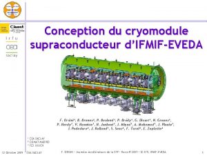
IFMIF SC HWR Cryomodule development F. Orsini 1, N. Bazin 1, P. Bosland 1, B. Branas 2, P. Brédy 1, P. Carbonnier 1, G. Disset 1, N. Grouas 1, P. Hardy 1, V. Hennion 1, E. Jacques 1, H. Jenhani 1, P. Mendez 2, J. Migne 1, Y. Pénichot 1, J. Plouin 1, I. Podadera 2, D. Regidor 2, J. Relland 1, B. Renard 1, D. Roudier 1, S. Sanz 2, F. Toral 2, E. Zaplatin 3 1 CEA-Saclay 2 nd March 2011 - CEA SACLAY France, 2 CIEMAT-Madrid Spain, 3 FZ-Julich Germany F. ORSINI – TTC Meeting - Milan

IFMIF Project (International Fusion Materials Irradiation Facility) Objective of the IFMIF project: characterization of materials with intense neutrons flux (1017 n/s) for the future Fusion Reactor DEMO (~150 dpa) 1 IFMIF accelerator IFMIF-EVEDA Prototype Accelerator Collaboration for Accelerator: CEA (FR), INFN (IT), CIEMAT (SP), SCK-CEN (BE), JAEA (JA) In the framework of an agreement between Euratom & Government of Japan, the program IFMIF/EVEDA has been launched in June 2007 2 nd March 2011 - CEA SACLAY F. ORSINI – TTC Meeting - Milan 2

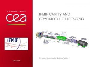
SRF Linac main parameters w~2. 0 m l~5 m HEBT Beam Dump LEBT MEBT RFQ h~2. 8 m SRF Linac Injector EVEDA General layout – Rokkasho site (JA) Objectives: transport and accelerate a 125 m. A Parameters D+ beam in CW, from 5 Me. V to 9 Me. V, with Frequency drift length as short as possible to deal with value of the HWR intense beam § 8 Superconducting Half Wave Resonators • low- HWRs = 0. 094, • working temperature 4. 4 K, • Accelerating field ~ 4. 5 MV/m max, § 8 RF power couplers § working mode CW, § RF power: 70 k. W per coupler (EVEDA cryomodule) and 200 k. W per coupler for IFMIF cryomodules 2 nd March 2011 § 8 Superconducting Solenoid Packages • focusing solenoid, • H&V steerers • cryogenic BPM § Cryostat with all necessary equipment - CEA SACLAY Accelerating field Ea Unloaded Quality factor Q 0 for Rs=20 n Beam aperture HWR / Solenoid Package Freq. range of HWR tuning syst Max. transmitted RF power by coupler (CW) External quality factor Qex Magnetic field Bz on axis max. Target Value Units 175 MHz 0. 094 4. 5 MV/m 1. 4× 10⁹ 40 / 50 mm ± 50 k. Hz 200 k. W 6. 3× 10⁴ 6 T B. dl on axis 1 T. m Field at cavity flange 20 m. T CBPM position accuracy 0. 25 mm 2 deg 18 / 120 W CBPM phase accuracy Total Static/Dynamic Heat losses F. ORSINI – TTC Meeting - Milan 3

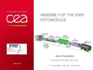
SRF Linac general layout Lhe input phase separator HWR equipped with Tuning System on top Solenoid Package equipped with VCCL Vacuum Vessel Magnetic shielding Thermal screen He phase separator Vacuum valve Lhe manifolds 2 nd March 2011 - CEA SACLAY "T" Transition Vacuum manifold and valve F. ORSINI – TTC Meeting - Milan Main support RF couplers 4

Half Wave Resonators Design RF Design Geometry Optimization Ep/Eacc=4. 4 & Bp/Eacc=10. 1 peak surface fields sufficiently reduced Thermo-mechanical studies Pressure calculations Max stress ~ 80 MPa OK 180 mm 0. 125 MPa nominal Final drawing of the HWR Prototype Coupler port 910 mm Tuning system port Mechanical stresses (in Pa) due to a 0. 25 MPa pressure 2 nd March 2011 - CEA SACLAY F. ORSINI – TTC Meeting - Milan "Naked" cavity 5

Half Wave Resonators realization & tests Ø Realization of two “naked” HWRs prototypes made by 2 different manufacturers (light differences in the manufacturing procedure) delivery Sept-Oct 2010 Ø Small problems encountered during realization BCP treatment solved rapidly, no consequence Ø Frequency out of range: FP 01=+245 k. Hz and FP 02=-85 k. Hz HPR Surface preparation @ IPN • BCP treatment (2. 4: 1: 1) • Temperature stabilized: 15°C to 17°C • ~130 µm Nb removal • HPR (multijets – 100 bars) • Clean room assembly • No baking on “naked” cavity Thanks to S. Bousson, F. Chatelet, C. Joly, R. Martret, G. Morel, G. Olry, P. Szott 2 nd March 2011 - CEA SACLAY F. ORSINI – TTC Meeting - Milan 6

Preliminary results of HWRs’vertical test Tests @ 4. 2 K @ IPN, pb with vacuum Ø problems of several multipacting barriers at low Eacc cavities not yet qualified Total nb of secondary e-/primary e- Ø Q 0 estimated from QL measurement ~1. 4× 10⁹ fulfill the requirements other barrier at ~250 k. V/m Excitation with RF pulses 1 rst barrier at ~73 k. V/m Ø Other tests with tuning system are expected soon 2 nd March 2011 - CEA SACLAY F. ORSINI – TTC Meeting - Milan 7

Tuning System Design RF Design and multipactor simulations Chosen Solution: capacitive plunger in central region large frequency range (> 50 k. Hz/mm) Tuner optimization Tuning sensitivity Multipactor simulations Thermo-mechanical studies Drawing of the Tuning System prototype Diameter around 250 mm Mechanical studies: deformation of the Nb. Ti plunger membrane of ± 1 mm constraints = 125 MPa Acceptable Flexible Nb membrane Connection to the He phase separator 2 nd March 2011 - CEA SACLAY Vessel filled with liquid helium F. ORSINI – TTC Meeting - Milan 8

Tuning System Realization & future tests Actuator part Dedicated testbench under preparation Step Motor Plunger part in Nb Screw Flexible Membrane Mechanical arm Lhe inlet and outlet HWR Plunger Dedicated testbench necessary to validate: Ø mechanical tests on the membrane (constraint gauges) max. amplitude without leakage, « fatigue » (many cycles of deformation) Ø thermal tests of the plunger+ membrane (thermal resistances to simulate power deposit on surface, temperature sensors) Ø validation of step motor and control system (LCS) 2 nd March 2011 - CEA SACLAY F. ORSINI – TTC Meeting - Milan 9

RF Power Coupler Design • Thermo mechanical studies of the whole coupler set in progress from July 2010 • Pre design ready simulations and results presented by manufacturer are in agreement with our Specifications With Courtesy of S. Einarson Mechanical deformation calculation: coupler + « T » transition, under vacuum Thermal calculation: temperature gradient on the ceramic Connection flange with cavity or matching box Connection bellows with vacuum tank Antenna 4 K, vacuum Cooled outer conductor RF window L < 100 µm max OK Ceramic T~ 6°C max OK 300 K, Patm • Validation of conception : Spring 2011 • realization of a complete mockup with a truncated antenna + a prototype of “T” RF transition: delivery foreseen in April’ 11 • Production of 2 couplers set (prototypes) delivery foreseen in November 2011 T Transition RF conditioning of couplers at CIEMAT from January 2012 2 nd March 2011 - CEA SACLAY F. ORSINI – TTC Meeting - Milan 10

Coupler Testbench Design RF Matching box : Couplers conditioning: Ø Good RF matching with “racetrack” design Ø Pumping port on side part Ø Diagnostic ports: photomultiplier and vacuum gauge two by two, at room temperature Water cooling Upstream coupler Downstream coupler RF Input RF Output e- pick-up photomult. gauge thermal meas. 1 photomultiplier 1 gauge Thermal measurements 1 1 1 2 Pumping port Matching box e- pick-up photomult. gauge thermal meas. With Courtesy of M. Chaibi 1 1 1 2 copper Stainless steel Pdiss=1. 5 k. W max Ø TW: from short pulses up to 200 k. W in continuous wave (IFMIF conditions) Ø SW: short pulses only, limited by the circulator load of the RF chain 2 nd March 2011 - CEA SACLAY The bandwidth for -30 d. B matching is around 4. 9 MHz F. ORSINI – TTC Meeting - Milan 11

Solenoid Package Design Magnetic design of solenoid 6 T B. dl ≥ 1 T. m Requirement 20 m. T at the cavity entrance Active shielding Magnetic field profile along beam axis Coils configuration Mechanical design and winding tests Vapor cooled current leads Active Shielding Secondary solenoid LHe vessel Dummy solenoid: validation of the winding procedure with copper wire (similar dim. than SC wire) HWR flange Steerer ~ 50 mm ~ 220 mm Solenoid ~ 240 mm 2 nd March 2011 - CEA SACLAY CBPM F. ORSINI – TTC Meeting - Milan 12

Cryostat Mechanical Design Magnetic shielding Thermal screen • Protection of cavities from the earth magnetic field (~500 m. G) • Cooled down at ~ 60 K by GHe • Implementation of the shielding plated against the vacuum tank wall: 1 -2 mm thick of mu-metal attenuation of the field < 10 m. G • Implementation of the screen : Aluminum sheets of 4 mm thick, equipped with soldered pipes Vacuum tank • Reinforced structure • Vertical and horizontal rods for the main frame • HWRs and Solenoid Packages • fixed on invar beam (beam axis direction) • supported by the frame on sliding attachments (vertical & lateral adjustments) Reinforced structure 0. 1 MPa 105 N/m 2 Al thermal screen Chimneys for cables output Internal conditions Temp <60 K (screen) P= 10 -6 Pa Soldered cooling circuit on door i 14 mm Doors 1 fixed point in the middle of the frame Soldered cooling circuit i 14 mm Access traps 2 nd March 2011 - CEA SACLAY RF couplers ports Hanging vertical rods F. ORSINI – TTC Meeting - Milan External conditions Temp 300 K <Patm 13

Cryogenic distribution for cryomodule Output phase separator Output of current leads (tbd) Output of HWRs and Solenoid Packages Output of coupler’s outer conductor an sfe rl in e Input phase separators Tr Input manifold of coupler’s jacket Input manifold of Solenoid Packages 2 nd March 2011 - CEA SACLAY Input manifold of HWRs F. ORSINI – TTC Meeting - Milan 14

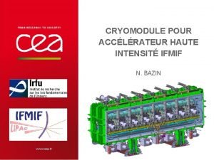
CBPM cryo-cables Internal view of the cryomodule Thermal screen He Phase Separator Access trap HWR um pip e Solenoid + steerers Magnets current leads Tuning system old Lh 2 nd March 2011 - CEA SACLAY if an m e RF coupler i Ma Va cu me ra nf old Lh if an m e F. ORSINI – TTC Meeting - Milan 15

Main Milestones of the project 2 nd March 2011 • Qualification of HWRs + magnets’ prototypes June 2011 • Start realization of HWRs of the series November 2011 • Conditioning of coupler’prototypes January 2012 • Start integration of cryomodule October 2013 • Cryomodule ready for shipment to Rokkasho October 2014 • Start commissioning of the complete accelerator July 2015 - CEA SACLAY F. ORSINI – TTC Meeting - Milan 16

Thank you for your attention 2 nd March 2011 - CEA SACLAY F. ORSINI – TTC Meeting - Milan 17

Cryoplant Schematic Diagram Maintain the nominal conditions for SC equipments in their vessel (He satured bath at T= 4. 4 K; P=0. 12 MPa) with static+dynamic heat losses Total request for the cryogenic system = 140 W + 50 l/h LHe LN 2 Tank (Consuming LN 2 only for pre-cooling) Helium Cryo-plant 150 W Helium compressor + ORS + gas buffer Phase separator High pressure He Ph. S Low pressure He Transfer line LHe+He gas LHe Dewar He refrigerator + Cold Box Valve Panel 300 K He gas SRF Linac Superconducting Cavities 2 nd March 2011 - CEA SACLAY Accelerator Vault F. ORSINI – TTC Meeting - Milan 18

Tuning System Options Jaw system: no space to be implemented • • Cavity Frequency = 175 MHz Tuning requirements: ± 50 k. Hz • Different cavity tuning systems studied: – Inductive plunger : not enough sensitivity – “Jaw” Tuning system: Plunger: not enough efficient – Deformation of the cavity around the beam axis with a jaw system – Large flange difficult to deform – Not enough space to implement such a system – Local cavity surface deformation: – Too high stress on the cavity surface – Not enough displacement Thin surface: too much stress, not enough tuning range New tuning system: a capacitive plunger in central region 2 nd March 2011 - CEA SACLAY F. ORSINI – TTC Meeting - Milan 19
 Plombieres kararları
 Trivia ag facility service
 Www.hwr.com
 Development that ended much development crossword
 Pattern development engineering
 Origin of community development
 Role of ngo in development communication
 Contemporary models of development and underdevelopment
 Septum interventriculare pars membranacea
 Deped financial management operations manual ppt
 Usda rural areas in massachusetts
 Product development and design ktu syllabus
 Digital revolution ppt
 Rapid game development
 Stages in the research process
 Gender and development concepts
 Development of surfaces of solids
 Database system development lifecycle
 Norwood development colorado springs
 Module 47 infancy and childhood cognitive development
