First DR FFT Results on Advanced LIGO Using


 The strain amplitude of")

 amplitude to 2. 66")


 amplitude to 2. 66")


- Slides: 16
First DR FFT Results on Advanced LIGO Using Perfect and Imperfect Optics By Ken Ganezer, George Jennings, and Sam Wiley CSUDH LIGO-G 020086 -00 -Z by Ken Ganezer March 22, 2002 LSC Meeting 12 LLO
MPI DR FFT and FFT in general are briefly documented on the Software Tools for AIC Web Site at http: //www. phys. ufl. edu/LIGO/STAIC. html. The source code and some shell scripts for MPI DR FFT are also available at this web site. Some MPI DR FFT results are also posted at http: //www. csudh. edu/neutrino/ligo. Please note that FFT is only capable of modeling a static interferometer (no dynamic effects). It does full field relaxations using pixelized grids in our case 256 x 256 pixels over a. 85 m x. 85 m. Fields are propagated using FFTs, thus the name.
ADVANCED LIGO SCHEMATIC WITH FFT FIELDS AND LENGTHS
FFT Advanced LIGO Input Parameters ( from Alan W. 11/01) The strain amplitude of the conjectured gravitational wave is hgw= 9. 99999999 E-22 Frequency (in Hz, displaced from Carrier) for which we optimize: On-Line FP Cav. , Off-Line FP Cav. , Power-Recyc. Cav. , Signal-Recyc. Cav. : 0. 0 250. 0 Base cavity lengths, L 1, (L 2+L 3)/2, L 4, L 5, L 6 : 3. 6276 4. 6225 4000. 0 4. 4063 Unbalancing length added for L 2, subtracted for L 3: The Unbalanced L 2, L 3: Lenchange = 0. 2082 4. 8307 4. 4143 1 Mirror Radius of Curvature for. . . Mrecyc -- 37335. 0 Mft -- 54261. 0 Mfr -- 54261. 0 Mtback -- 54261. 0 Mrback -- 54261. 0 Mdual -- 37325. 0 Beam Spot Size at On-Line FP-Input Mirror = 5. 996000000 E-02 Beam Curv. Radius at On-Line FP-Input Mirror = Width of square calculational window: 54261. 0 0. 850211 Mirror diaphragms (r 1, r 2, r 3, r 4, r 5, rbs_x, rbs_y, r 6) : 0. 23 0. 3252691 0. 23
Base REF-Side intensity reflectivities -r_ref 2, r_ref 3, pow_r_refbs, ref 4, ref 5, ref 6 : 0. 9949625 0. 4999625 0. 9999475 0. 9299625 Base AR-Side intensity reflectivities -- ar_ref 2, ar_ref 3, pow_ar_refbs : 0. 9949625 0. 4999625 Base losses in recycling mirror, on-line & splitter, on- & off-line back mirrors, and 3. 750000000000000 E-05 3. 750000000 E-05 off-line input mirrors, beam dual recycling mirror: 3. 750000000000000 E-05 Calculated Intensity Transmissions (Both Sides) -T_recyc(initial), T_online_inp, T_offline_inp, T_splitter, T_online_back, T_offline _back, T_dual: 5. 99999996 E-02 5. 000000000000028 E-03 0. 5 1. 500000000001087 E-05 6. 99999998 E-02
Phase deformations of all surfaces from 0 nm (perfect surfaces) amplitude to 2. 66 nm (λlaser/400).
Comparison of FFT Advanced LIGO Powers With Analytical Calculations Using Bench For Perfect Optics • Some power at asymmetric port • Slight Asymmetry of Power in Arms and Shortfall in PRC Relaxed Phases at Carrier Frequency Final Off-resonance phase in Recycling Cav: 1. 454288558994578 E-06 Final Off-resonance phase in On-Line Arm Cav: -3. 828252751282112 E-11 Final Off-resonance phase in Off-Line Arm Cav: 1. 263516982215558 E-11 Final Off-resonance phase in Signal-Recycling Cav: 6. 562120287199626 E-06 Deviation of Final Dark-Fringe Phase from Pi: -4. 166691938145561 E-07 Interferometer is Slightly Unbalanced
We First Consider the Case of All Imperfect Optics; Thus Both Surfaces and Substrates Have Pixel by Pixel Phase Deformations Respectively of Reflected and Transmitted Fields of Amplitude D= 2. 66 nm Here we characterize the effects of pixel-by-pixel phase deformations on Advanced LIGO intensity distributions. Carrier fields are given (Figure-2 a) inside the in-line FP arms and (Figure-2 b) at the asymmetric BS port. Cases (at the top of 2 a and 2 b) of an interferometer with relatively large deformations of maximum D= laser /400=2. 66 nm are compared with (at the bottom of 2 a and 2 b) the same fields for an interferometer with perfect mirrors (D=0 nm). A uniformly distributed random number between +D and –D is added to the phase of imperfect mirror pixels. Figure-1 contains definitions of the fields that are studied in our simulations for the carrier and for each gravitational wave sideband. We Considered Cases of Phase Deformations of all 17 Surfaces and Substrates Deformed and of Each Surface or Substrate being Deformed While the Other 16 Remained Perfect. For Each of these 18 Cases GW sidebands were studied at + 250, -250, +100, and – 100 Hz. Six different Deformation Amplitudes were used from 0 nm to 2. 66 nm. About Fifteen IFO Performance Parameters were Compiled for all of these cases in a large spreadsheet. Please Note that DR FFT Does Not Yet Include Modulation Sidebands.
I Figure-2 a. Electric Field Intensity Map and Profile for the carrier in the FP arm on the reflective side of the BS. Perfect on top D= 2. 66 nm on Bottom Figure-2 b. Intensity at the asymmetric port of the BS, Top is Perfect case bottom is D=2. 66 nm
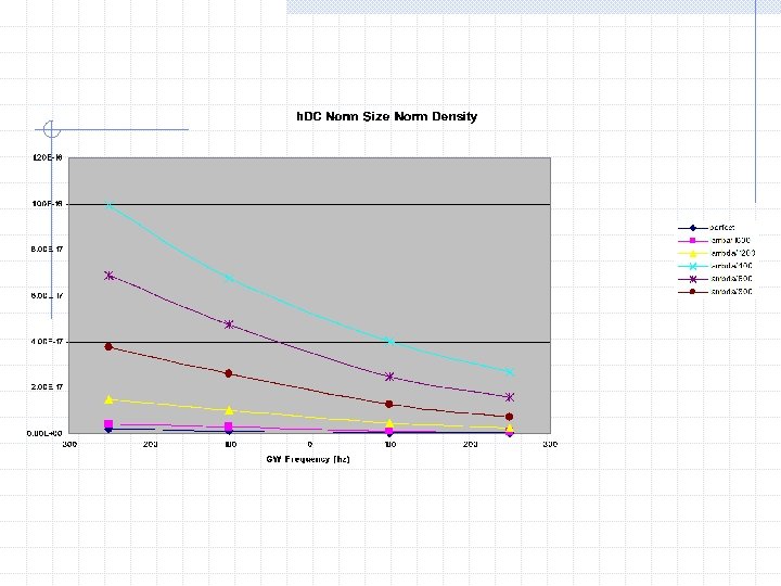
DR FFT Calculates the Power in All Specified GW Sidebands
Phase deformations of all surfaces from 0 nm (perfect surfaces) amplitude to 2. 66 nm (λlaser/400).
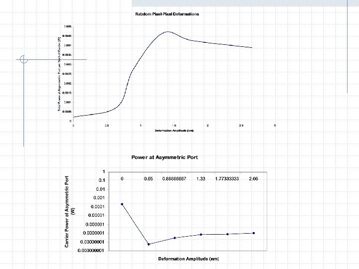
Phase Deformations of the reflecting surface of the Offline FP back mirror from 0 nm to 2. 66 nm maximum; all other surfaces and substrates perfect.
Some Very Preliminary Conclusions The Current Specifications for Advanced LIGO lead to a slightly unbalanced interferometer (in which there is some light at the asymmetric port) when modeled with DR FFT with and without the Schnupp Asymmetry. Perhaps we (the DR FFT modelers) have misunderstood something. For deformation amplitude of about. 6 nm ( laser/ 1600) or less the performance of Advanced LIGO is not diminished greatly (by more than 10%). This result might be used to set tolerances for large spatial frequency deformations for Advanced LIGO mirrors of 1 nm or less (deformations must be smaller than 1 nm). From studies in which all surfaces and substrates were phase deformed and the tests of individual phase deformations, it is clear that the interferometer is highly sensitive to deformations of the test masses and only mildly sensitive to deformations of other optics. Power in the Arms and Cavities is significantly reduced when a single test mass surface or substrate undergoes sizable phase deformations. Intensity Maps and Profiles in the SRC are Badly Distorted When Imperfect Optics with large deformations of all surfaces and substrates are Included. Scattered Light is Significant in this Case. For other cavities lots of power is lost for large deformations but maps and profiles are not badly distorted.