FEA on the Conceptual Design of the FPIX

- Slides: 26
FEA on the Conceptual Design of the FPIX substrate for the CMS upgrade C. M. Lei Simon Kwan 10/07/08 CMS Pixel Mechanical Upgrade Substrate Cooling FEA 10/07/08 1
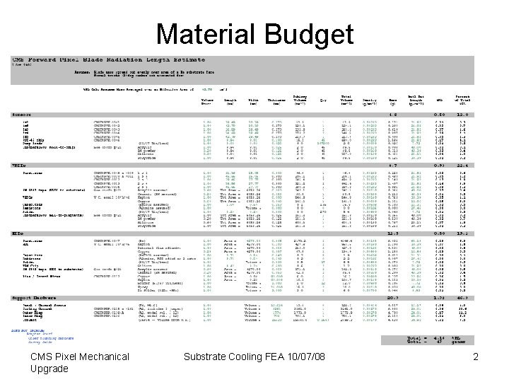
Material Budget CMS Pixel Mechanical Upgrade Substrate Cooling FEA 10/07/08 2
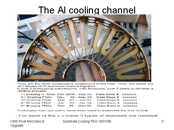
The Al cooling channel CMS Pixel Mechanical Upgrade Substrate Cooling FEA 10/07/08 3
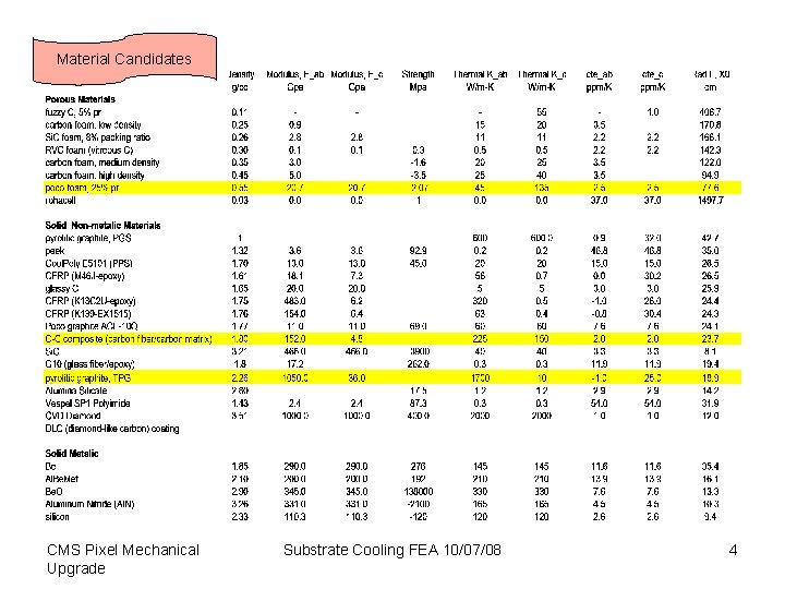
Material Candidates CMS Pixel Mechanical Upgrade Substrate Cooling FEA 10/07/08 4
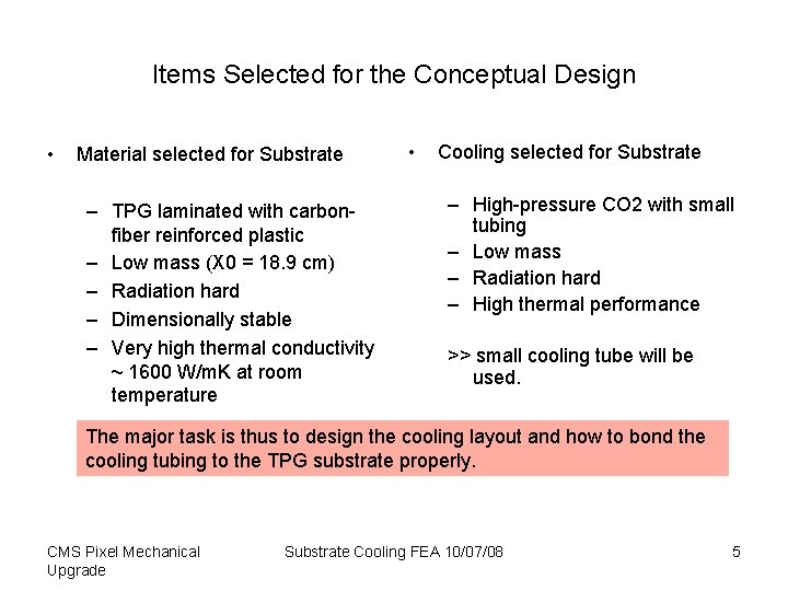
Items Selected for the Conceptual Design • Material selected for Substrate – TPG laminated with carbonfiber reinforced plastic – Low mass (X 0 = 18. 9 cm) – Radiation hard – Dimensionally stable – Very high thermal conductivity ~ 1600 W/m. K at room temperature • Cooling selected for Substrate – High-pressure CO 2 with small tubing – Low mass – Radiation hard – High thermal performance >> small cooling tube will be used. The major task is thus to design the cooling layout and how to bond the cooling tubing to the TPG substrate properly. CMS Pixel Mechanical Upgrade Substrate Cooling FEA 10/07/08 5
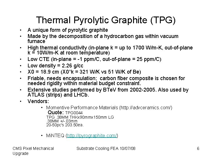
Thermal Pyrolytic Graphite (TPG) • • • A unique form of pyrolytic graphite Made by the decomposition of a hydrocarbon gas within vacuum furnace High thermal conductivity (in-plane k = up to 1700 W/m-K, out-of-plane k = 10 W/m-K at room temperature) Low CTE (in-plane = -1 ppm/C, out-of-plane = 25 ppm/C) Low density = 2. 26 g/cc X 0 = 18. 9 cm (X 0*k = 321 W/K vs 51 W/K of Be) Friable, needs encapsulation; carbon fiber composite is chosen for needed rigidity within material budget constraint. Extensive studies performed by BTe. V from 2002 -2005. Also used by ATLAS (strips) and LHCb. Vendors: • Momentive Performance Materials (http: //advceramics. com/) Quote: TPG 0044 TPG. 38 MM THKx 90 mmx 150 mm LG. 38 MM +/-. 03 mm 20 -50 pc's 203. 50 ea. • Mi. NTEQ (http: //pyrographite. com/) CMS Pixel Mechanical Upgrade Substrate Cooling FEA 10/07/08 6
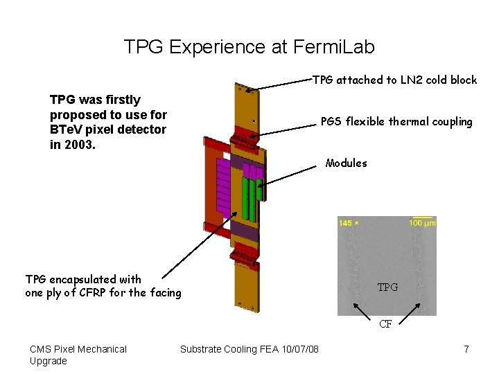
TPG Experience at Fermi. Lab TPG attached to LN 2 cold block TPG was firstly proposed to use for BTe. V pixel detector in 2003. PGS flexible thermal coupling Modules TPG encapsulated with one ply of CFRP for the facing TPG CF CMS Pixel Mechanical Upgrade Substrate Cooling FEA 10/07/08 7
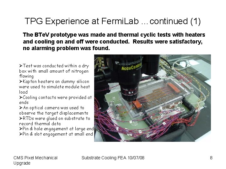
TPG Experience at Fermi. Lab …continued (1) The BTe. V prototype was made and thermal cyclic tests with heaters and cooling on and off were conducted. Results were satisfactory, no alarming problem was found. ØTest was conducted within a dry box with small amount of nitrogen flowing ØKapton heaters on dummy silicon were used to simulate module heat load ØCooling contacts were provided at ends ØAn optical camera was used to observe the target displacements ØRTDs were glued on substrate to record thermal data ØPin & hole engagement at large end ØPin & slot engagement at small end CMS Pixel Mechanical Upgrade Substrate Cooling FEA 10/07/08 8
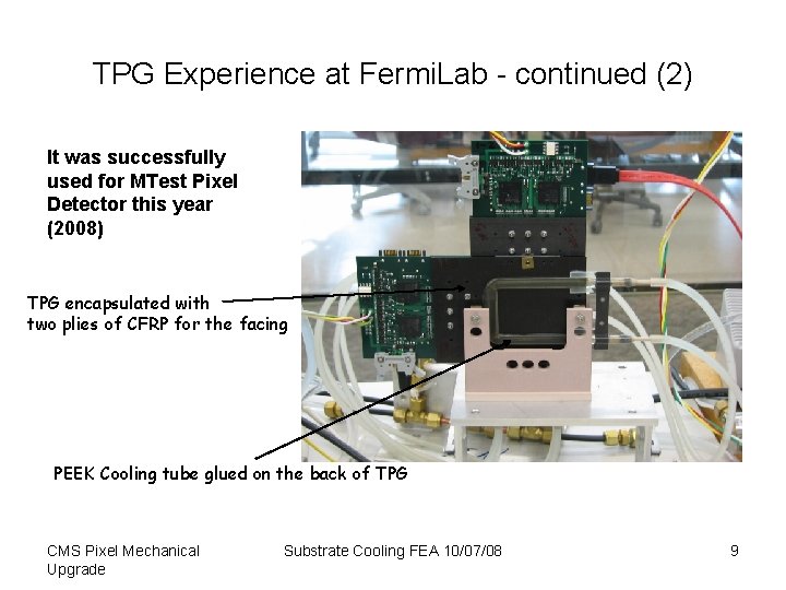
TPG Experience at Fermi. Lab - continued (2) It was successfully used for MTest Pixel Detector this year (2008) TPG encapsulated with two plies of CFRP for the facing PEEK Cooling tube glued on the back of TPG CMS Pixel Mechanical Upgrade Substrate Cooling FEA 10/07/08 9
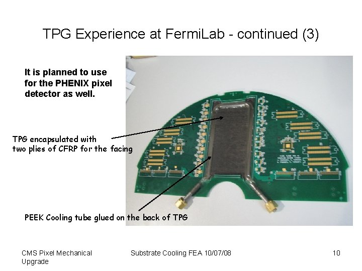
TPG Experience at Fermi. Lab - continued (3) It is planned to use for the PHENIX pixel detector as well. TPG encapsulated with two plies of CFRP for the facing PEEK Cooling tube glued on the back of TPG CMS Pixel Mechanical Upgrade Substrate Cooling FEA 10/07/08 10
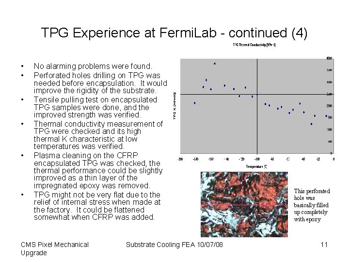
TPG Experience at Fermi. Lab - continued (4) • • • No alarming problems were found. Perforated holes drilling on TPG was needed before encapsulation. It would improve the rigidity of the substrate. Tensile pulling test on encapsulated TPG samples were done, and the improved strength was verified. Thermal conductivity measurement of TPG were checked and its high thermal K characteristic at low temperatures was verified. Plasma cleaning on the CFRP encapsulated TPG was checked, thermal performance could be slightly improved as a thin layer of the impregnated epoxy was removed. TPG might not be very flat due to the relief of internal stress when made at the factory. It could be flattened somewhat when CFRP was added. CMS Pixel Mechanical Upgrade Substrate Cooling FEA 10/07/08 This perforated hole was basically filled up completely with epoxy 11
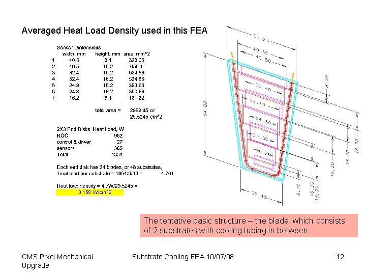
Averaged Heat Load Density used in this FEA The tentative basic structure – the blade, which consists of 2 substrates with cooling tubing in between. CMS Pixel Mechanical Upgrade Substrate Cooling FEA 10/07/08 12
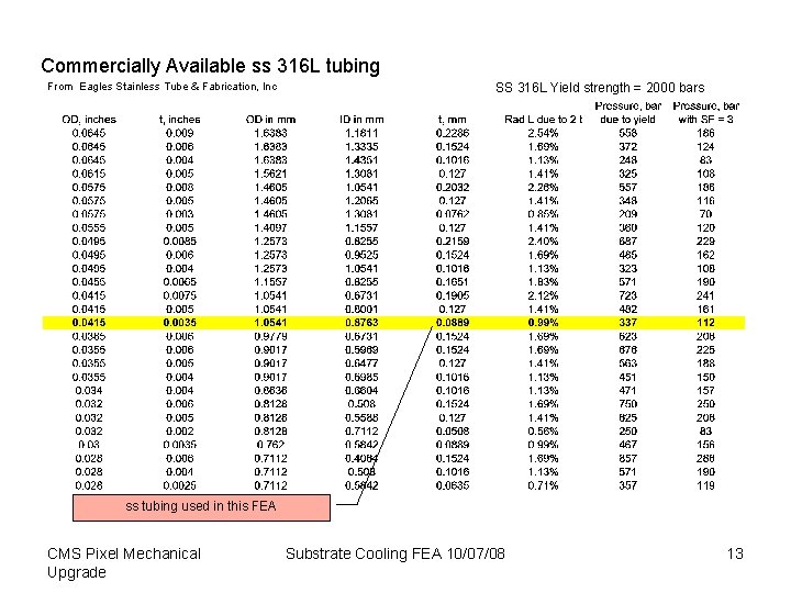
Commercially Available ss 316 L tubing From Eagles Stainless Tube & Fabrication, Inc SS 316 L Yield strength = 2000 bars ss tubing used in this FEA CMS Pixel Mechanical Upgrade Substrate Cooling FEA 10/07/08 13
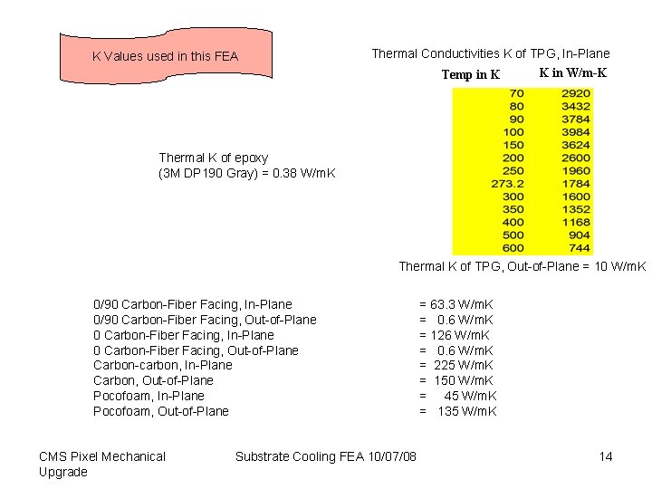
K Values used in this FEA Thermal Conductivities K of TPG, In-Plane K in W/m-K Temp in K Thermal K of epoxy (3 M DP 190 Gray) = 0. 38 W/m. K Thermal K of TPG, Out-of-Plane = 10 W/m. K 0/90 Carbon-Fiber Facing, In-Plane 0/90 Carbon-Fiber Facing, Out-of-Plane 0 Carbon-Fiber Facing, In-Plane 0 Carbon-Fiber Facing, Out-of-Plane Carbon-carbon, In-Plane Carbon, Out-of-Plane Pocofoam, In-Plane Pocofoam, Out-of-Plane CMS Pixel Mechanical Upgrade Substrate Cooling FEA 10/07/08 = 63. 3 W/m. K = 0. 6 W/m. K = 126 W/m. K = 0. 6 W/m. K = 225 W/m. K = 150 W/m. K = 45 W/m. K = 135 W/m. K 14
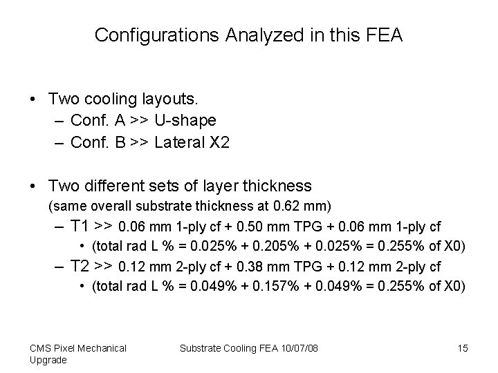
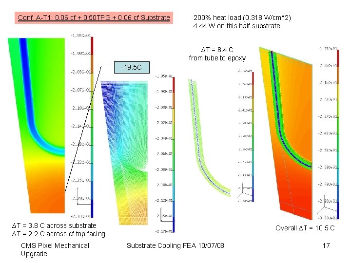
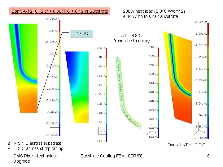
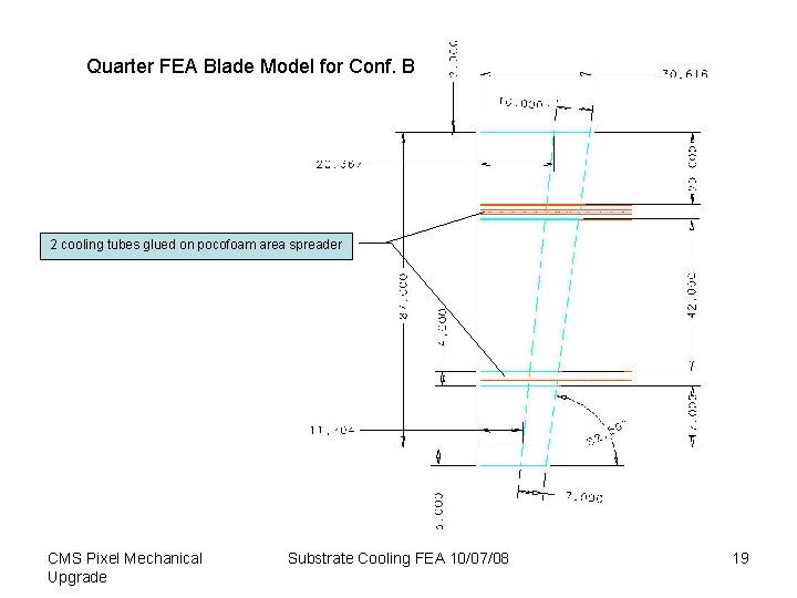
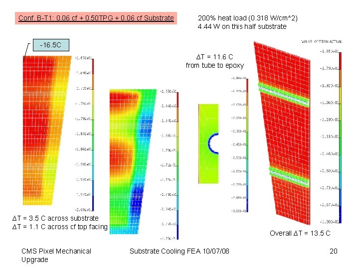
Configurations Analyzed in this FEA • Two cooling layouts. – Conf. A >> U-shape – Conf. B >> Lateral X 2 • Two different sets of layer thickness (same overall substrate thickness at 0. 62 mm) – T 1 >> 0. 06 mm 1 -ply cf + 0. 50 mm TPG + 0. 06 mm 1 -ply cf • (total rad L % = 0. 025% + 0. 205% + 0. 025% = 0. 255% of X 0) – T 2 >> 0. 12 mm 2 -ply cf + 0. 38 mm TPG + 0. 12 mm 2 -ply cf • (total rad L % = 0. 049% + 0. 157% + 0. 049% = 0. 255% of X 0) CMS Pixel Mechanical Upgrade Substrate Cooling FEA 10/07/08 15
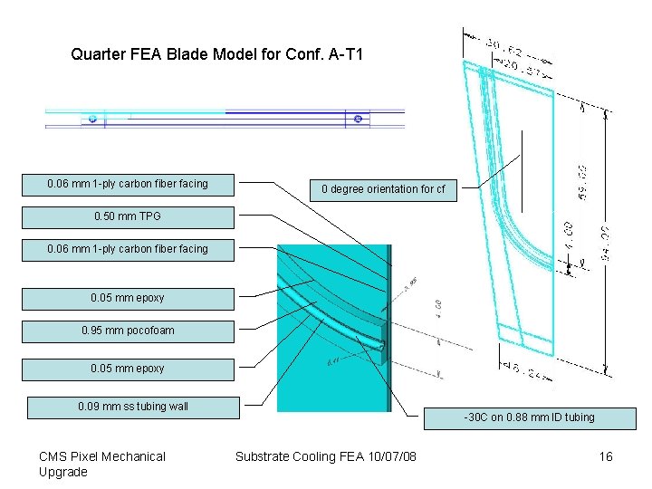
Quarter FEA Blade Model for Conf. A-T 1 0. 06 mm 1 -ply carbon fiber facing 0 degree orientation for cf 0. 50 mm TPG 0. 06 mm 1 -ply carbon fiber facing 0. 05 mm epoxy 0. 95 mm pocofoam 0. 05 mm epoxy 0. 09 mm ss tubing wall CMS Pixel Mechanical Upgrade -30 C on 0. 88 mm ID tubing Substrate Cooling FEA 10/07/08 16
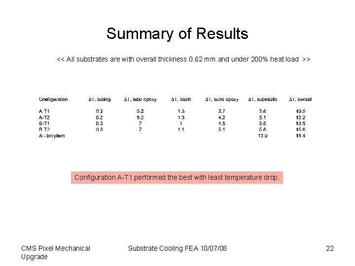
Conf. A-T 1: 0. 06 cf + 0. 50 TPG + 0. 06 cf Substrate 200% heat load (0. 318 W/cm^2) 4. 44 W on this half substrate ∆T = 8. 4 C from tube to epoxy -19. 5 C ∆T = 3. 8 C across substrate ∆T = 2. 2 C across cf top facing CMS Pixel Mechanical Upgrade Overall ∆T = 10. 5 C Substrate Cooling FEA 10/07/08 17
Conf. A-T 2: 0. 12 cf + 0. 38 TPG + 0. 12 cf Substrate -17. 8 C 200% heat load (0. 318 W/cm^2) 4. 44 W on this half substrate ∆T = 8. 8 C from tube to epoxy ∆T = 5. 1 C across substrate ∆T = 3 C across cf top facing CMS Pixel Mechanical Upgrade Overall ∆T = 12. 2 C Substrate Cooling FEA 10/07/08 18
Quarter FEA Blade Model for Conf. B 2 cooling tubes 2 cooling glued tubes on pocofoam glued onarea pocofoam spreader CMS Pixel Mechanical Upgrade Substrate Cooling FEA 10/07/08 19
Conf. B-T 1: 0. 06 cf + 0. 50 TPG + 0. 06 cf Substrate 200% heat load (0. 318 W/cm^2) 4. 44 W on this half substrate -16. 5 C ∆T = 11. 6 C from tube to epoxy ∆T = 3. 5 C across substrate ∆T = 1. 1 C across cf top facing CMS Pixel Mechanical Upgrade Overall ∆T = 13. 5 C Substrate Cooling FEA 10/07/08 20
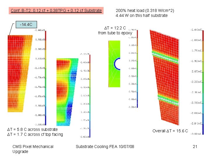
Conf. B-T 2: 0. 12 cf + 0. 38 TPG + 0. 12 cf Substrate -14. 4 C 200% heat load (0. 318 W/cm^2) 4. 44 W on this half substrate ∆T = 12. 2 C from tube to epoxy ∆T = 5. 8 C across substrate ∆T = 1. 7 C across cf top facing CMS Pixel Mechanical Upgrade Overall ∆T = 15. 6 C Substrate Cooling FEA 10/07/08 21
Summary of Results << All substrates are with overall thickness 0. 62 mm and under 200% heat load >> Configuration A-T 1 performed the best with least temperature drop. CMS Pixel Mechanical Upgrade Substrate Cooling FEA 10/07/08 22
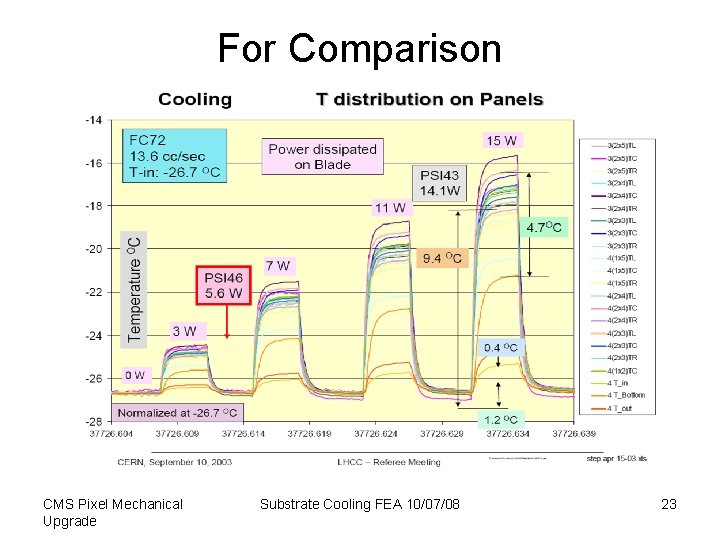
For Comparison CMS Pixel Mechanical Upgrade Substrate Cooling FEA 10/07/08 23
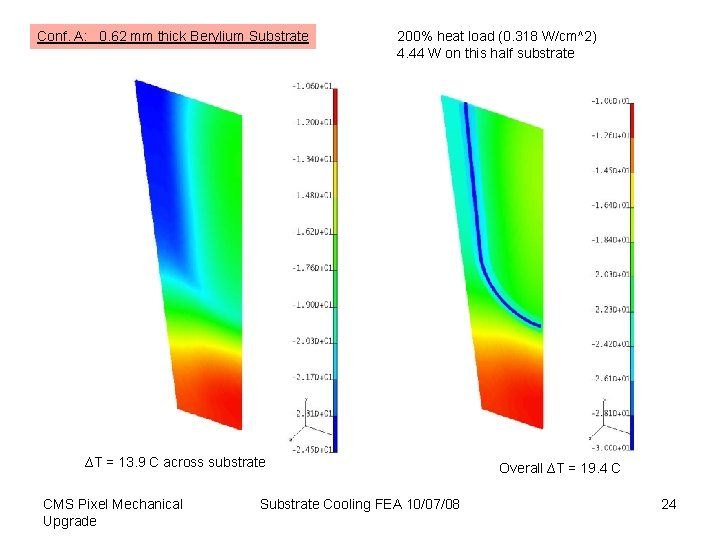
Conf. A: 0. 62 mm thick Berylium Substrate 200% heat load (0. 318 W/cm^2) 4. 44 W on this half substrate -19. 5 C ∆T = 13. 9 C across substrate CMS Pixel Mechanical Upgrade Substrate Cooling FEA 10/07/08 Overall ∆T = 19. 4 C 24
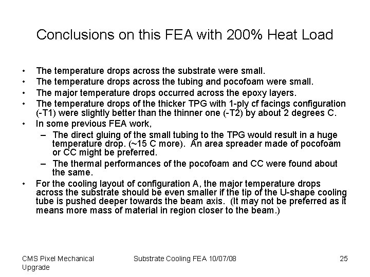
Conclusions on this FEA with 200% Heat Load • • • The temperature drops across the substrate were small. The temperature drops across the tubing and pocofoam were small. The major temperature drops occurred across the epoxy layers. The temperature drops of the thicker TPG with 1 -ply cf facings configuration (-T 1) were slightly better than the thinner one (-T 2) by about 2 degrees C. In some previous FEA work, – The direct gluing of the small tubing to the TPG would result in a huge temperature drop. (~15 C more). An area spreader made of pocofoam or CC might be preferred. – The thermal performances of the pocofoam and CC were found about the same. For the cooling layout of configuration A, the major temperature drops across the substrate should be even smaller if the tip of the U-shape cooling tube is pushed deeper towards the beam axis. (It may not be preferred as it means more mass of material in region closer to the beam. ) CMS Pixel Mechanical Upgrade Substrate Cooling FEA 10/07/08 25
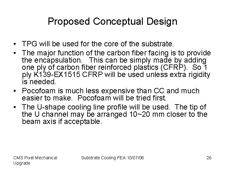
Proposed Conceptual Design • TPG will be used for the core of the substrate. • The major function of the carbon fiber facing is to provide the encapsulation. This can be simply made by adding one ply of carbon fiber reinforced plastics (CFRP). So 1 ply K 139 -EX 1515 CFRP will be used unless extra rigidity is needed. • Pocofoam is much less expensive than CC and much easier to make. Pocofoam will be tried first. • The U-shape cooling line profile will be used. The tip of the U channel may be arranged 10~20 mm closer to the beam axis if acceptable. CMS Pixel Mechanical Upgrade Substrate Cooling FEA 10/07/08 26