Physical Database Design 1 Conceptual database design The

Physical Database Design 1

Conceptual database design • The process of constructing a model of the information used in an enterprise, independent of all physical considerations. Conceptual database design is entirely independent of implementation details such as the target DBMS, application programs, programming languages, hardware platform, performance issues, or any other physical consideration. 2

Logical database design • The process of constructing a model of the information used in an enterprise based on a specific data model, but independent of a particular DBMS and other physical considerations. 3

Physical database design • The process of producing a description of the implementation of the database on secondary storage; it describes the base relations, file organizations, and indexes used to achieve efficient access to the data, and any associated integrity constraints and security measures. 4

Physical database design • The physical database design is tailored to a specific DBMS. There is feedback between physical and logical design, because decisions taken during physical design for improving performance may affect the logical data model. 5

Physical database design steps 1. Translate global logical data model for target DBMS 2. Design physical representation 3. Design user views 4. Design security mechanisms 5. Consider the introduction of controlled redundancy 6. Monitor and tune the operational system 6

1. Translate Global Logical Data Model for Target DBMS • This process requires knowledge of the functionality offered by the target DBMS. For example, the designer need to know: – How to create base relations – Whether the system supports the definition of primary keys, foreign keys, and alternate keys; – Whether the system allows attributes to be defined as NOT NULL – Whether the system supports the definition of domains, integrity constraints, and enterprise constraints. 7

Three activities of Translate Global Logical Data Model for Target DBMS § Design base relations § Design representation of derived data § Design enterprise constraints 8

Design base relations • • the name of the relation a list of simple attributes the primary key, alternate keys, and foreign keys a list of any derived attributes and how they should be computed referential integrity constraints for any foreign keys identified its domain, consisting of a data type, length, and any constraints on the domain an optional default value for the attribute whether the attribute can hold nulls 9

Design representation of derived data • Derived attributes do not appear in the logical data model but are documented in the data dictionary. • The designer should calculate: – the additional cost to store the derived data and keep it consistent with operational data from which it is derived; – the cost to calculate it each time it is required 10

Design enterprise constraints • CONSTRAINT staffnothandlingtoomuch CHECK ( NOT EXISTS ( SELECT staffno FROM property. For. Rent GROUP BY staff. No HAVING COUNT(*) > 100 ) ) 11

2. Design Physical Representation Objective To determine the optimal file organizations to store the base relations and the indexes that are required to achieve acceptable performance, that is, the way in which relations and tuples will be held on secondary storage. 12

Factors used to measure efficiency • Transaction throughput The number of transaction that can be processed in a given time. • Response time The elapsed time for the completion of a single transaction. • Disk storage The amount of disk space required to store the database files. 13

The four basic hardware components • The four basic hardware components interact and affect system performance: – – Main memory CPU Disk I/O Network 14

Disk I/O • The O/S files should be separated from the database files • The main data base files should be separated from the index files • The recovery log file should be separated from the rest of the database O/S Main database file Index file Recovery log file 15

Design physical representation activities § § Analyze transactions Choose file organizations Choose indexes Estimate disk space requirements 16

Analyze Transaction Objective To understand the functionality of the transactions that will run on the database and to analyze the important transactions. 17

Analyze Transaction In analyzing the transactions, we attempt to identify performance criteria, such as • The transactions that run frequently and will have a significant impact on performance • The transactions that are critical to the operation of the business • The times during the day/week when there will be a high demand made on the database (called the peak load) 18

Choose file organizations • In many cases, a relational DBMS may give little or no choice for choosing file organizations. 19

File Organization and Storage Structures Basic Concepts Staff. No Name Position SL 21 White Manager SG 37 Beech Assistant SG 14 Ford Supervisor SA 9 Howe Assistant SG 5 Brand Manager SL 41 Lee Assistant Page 1 2 20
 files • Sequential (ordered) files")
The main types of file organization • Heap (unordered) files • Sequential (ordered) files • Hash files 21

Heap File • Records are placed in the file in the order as they are inserted. • Linear search must be performed to access method. • To delete record – the required page has to be retrieved, the record marked as deleted, and the page written back to disk. • This means that heap files have to be periodically reorganized by the DBA. • Heap files are one of the best organization for bulk loading data into a table. 22
 files • The records in a file can be sorted on the")
Sequential (ordered) files • The records in a file can be sorted on the values of one or more of the fields Example – order field: Staff No SELECT * FROM staff ORDERBY staffno; SELECT * FROM staff WHERE staffno = ‘SG 37’; binary search SA 9 SG 5 SG 14 SG 37 SL 21 SL 41 (1) (3) (2) 23
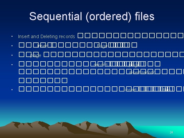
 files ������� insert • ����� Temporary unsorted file ������ overflow ���� transaction")
Sequential (ordered) files ������� insert • ����� Temporary unsorted file ������ overflow ���� transaction file • ����� insert �� overflow • ���� Retrieve ����� main file ������� overflow ����� linear search • DBA ������ merge ������� main file ��� overflow ���� 25

Hash Files • A hash function calculates the address of the pages. • The base field is called the hash field • Techniques used to calculate are folding and division-remainder 26

Folding Technique • Folding technique �������� Example: S U R A T 19 21 18 01 20 PAGE ทเกบขอมล 1921+180120=182041 27

Division-remainder • Division-remainder �������� Example: Product No. 120 page �������� 117 / 13 = 9 ��� 3 ตำแหนงทเกบขอมล 28
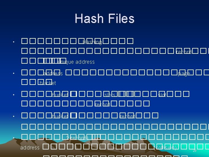

�������� collision �� hash file • • Open addressing Unchained overflow Chained overflow Multiple hashing 30

Collision resolution using Open Addressing Before ID 1658 ID 6546 ID 0345 Bucket 0 1 After ID 1658 ID 6546 ID 0345 Bucket 0 1 ID 4555 ID 2215 ID 3254 2 สมมตเราตองการ insert record ID 4555 ซงจาก Hash function คำนวณแลวจะตองอย bucket ท 2 แต bucket ท 2 เตมแลวจง หา bucket ทวาง แลวจงนำไป insert ท bucket นนในทนกคอ bucket ท 1 นนเอง scan 31

Collision resolution using unchained overflow Before ID 1658 ID 6546 ID 0345 ID 2215 ID 3254 Bucket 0 1 Overflow area Bucket ID 4555 3 4 2 ไมวา record ใดหากคำนวณโดย Hash function แลวเกด collision แลวจะนำไปเกบไวใน overflow area ซงกคอ bucket ท 3 และ 4 เมอมการคนขอมลใน area หลกไมเจอ จะไปหาในบรเวณ overflow area 32

Collision resolution using chained overflow Before ID 1658 ID 6546 ID 0345 ID 2215 ID 3254 Bucket 0 0 0 1 3 2 Overflow area Bucket ID 4555 3 4 สมมตเราตองการ insert record ID 4555 ซงจาก Hash function คำนวณแลวจะตองอย bucket ท 2 แต bucket ท 2 เตมแลวจง insert row ID 4555 ลงใน overflow area คอ bucket ท 3 โดยท bucket หลกจะม synonym pointer ชไปท bucket ท 3 อาจม technique อนอก เชนแทนทจะชไปท bucket แตจะชไปท slot address แทน 33

Multiple hashing • ����� hashing function ����������� hashing function ������� 34

Indexes Index A data structure that allows the DBMS to locate particular records in a file more quickly and thereby speed response to user queries 36

Dense Index Supplier file (data( S 1 Smith 20 S 2 Jones 10 S 3 Blake 30 S 4 Clark 20 S 5 Adams 30 London Paris London Athens 37

Dense Index City file (index( Athens London Paris Supplier file (data( S 1 Smith 20 S 2 Jones 10 S 3 Blake 30 S 4 Clark 20 S 5 Adams 30 London Paris London Athens 38

Index • Advantage : Speed up Retrieval • Disadvantage : Slow down update 39

Nondense index S# index S 2 S 4 S 5 Supplier file (data( S 1 Smith 20 London S 2 Jones 10 Paris S 3 Blake 30 Paris S 4 Clark 20 London S 5 Adams 30 Athens Page P-1 Page P+1 40

B-trees 12 6 8 12 15 18 32 32 35 40 50 51 52 52 50 82 58 70 60 62 70 Index set 89 71 78 82 83 85 89 94 91 93 94 96 97 99 Sequence set 41

Clustered Tables • Clusters are groups of one or more tables physically stored together because they share common columns. 42

Clustered Tables Tel Dname Deptid Emp# Ename Dob 2234 Accounting AC 2088 Marketing MK 101 103 108 102 104 Smith Tony Mike Mary Tom 23/4/80 09/2/83 12/8/85 17/7/75 29/1/82 Employee Department Cluster key 43
- Slides: 43