ERROR DETECTION AND CORRECTION 350151 Digital Circuit 1
- Slides: 15
ERROR DETECTION AND CORRECTION 350151 – Digital Circuit 1 Choopan Rattanapoka
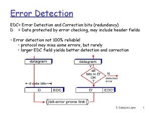
Problems and Solution Some problems may occur when you transmit digital data. (such as noise) Thus, the solution that can prevent incorrect digital data during the transmission are Error Detection the ability to detect the presence of errors caused by noise or other impairments during transmission from the transmitter to the receiver Error the Correction additional ability to reconstruct the original, errorfree data.
Error Detection There are several schemes exist to achieve error detection, and they are quite simple. We need to transmit more bits than in the original data. Example of error detection schemes Repetition schemes Parity schemes Checksum Cyclic redundancy checks Hamming distance based checks Hash function Horizontal and vertical redundancy check
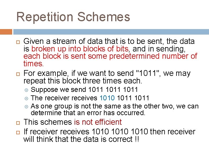
Repetition Schemes Given a stream of data that is to be sent, the data is broken up into blocks of bits, and in sending, each block is sent some predetermined number of times. For example, if we want to send "1011", we may repeat this block three times each. Suppose we send 1011 The receiver receives 1010 1011 As one group is not the same as the other two, we can determine that an error has occurred. This schemes is not efficient If receiver receives 1010 then receiver will think that the data is correct !!
Parity Schemes (1) There are 2 types of parity error detection: Even parity schemes Odd parity schemes The stream of data is broken up into blocks of bits, and the number of 1 bits is counted. We add an extra bit called parity bit during the transmission
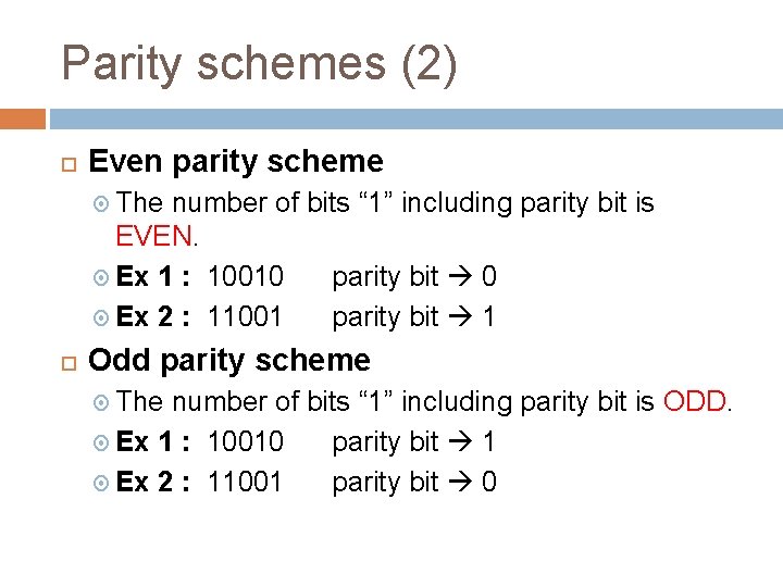
Parity schemes (2) Even parity scheme The number of bits “ 1” including parity bit is EVEN. Ex 1 : 10010 parity bit 0 Ex 2 : 11001 parity bit 1 Odd parity scheme The number of bits “ 1” including parity bit is ODD. Ex 1 : 10010 parity bit 1 Ex 2 : 11001 parity bit 0
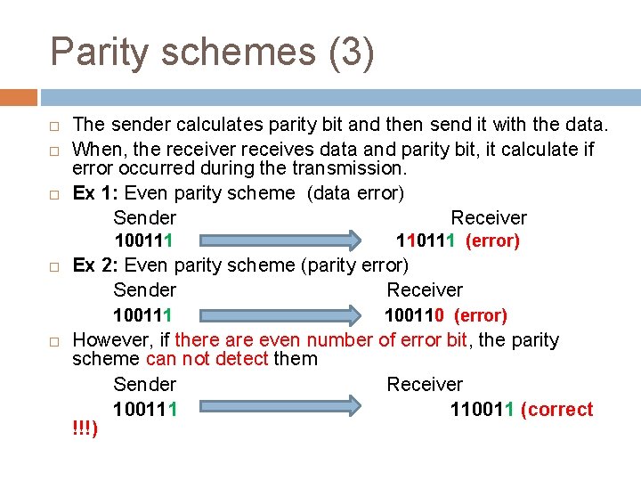
Parity schemes (3) The sender calculates parity bit and then send it with the data. When, the receiver receives data and parity bit, it calculate if error occurred during the transmission. Ex 1: Even parity scheme (data error) Sender Receiver 100111 Ex 2: Even parity scheme (parity error) Sender Receiver 100111 110111 (error) 100110 (error) However, if there are even number of error bit, the parity scheme can not detect them Sender Receiver 100111 110011 (correct !!!)
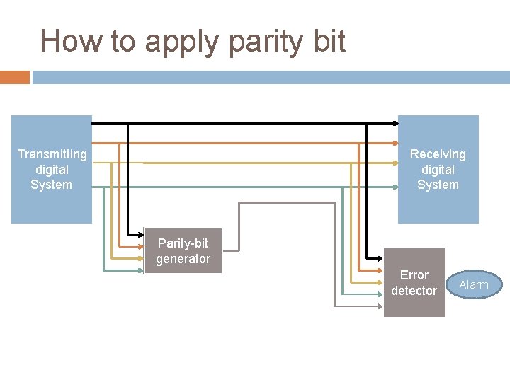
How to apply parity bit Transmitting digital System Receiving digital System Parity-bit generator Error detector Alarm
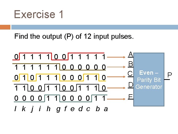
Exercise 1 Find the output (P) of 12 input pulses. 0 1 0 l 1 1 0 k 1 1 0 0 0 j 1 1 1 0 0 i 1 1 1 h 0 0 1 0 1 0 g f 1 0 0 e 1 0 0 1 0 d 1 0 1 1 0 c 1 1 0 0 1 0 1 1 b a A B C Even – Parity Bit D Generator E P
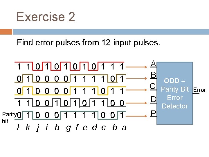
Exercise 2 Find error pulses from 12 input pulses. 1 0 0 1 Parity 0 bit l 1 1 1 k 0 0 0 j 1 0 0 i 0 0 0 1 0 h 1 0 0 1 0 1 1 1 g f 1 1 1 0 1 e 0 1 1 d 1 1 0 c 1 1 0 1 1 1 0 0 0 1 b a A B ODD – C Parity Bit D Error P Detector Error
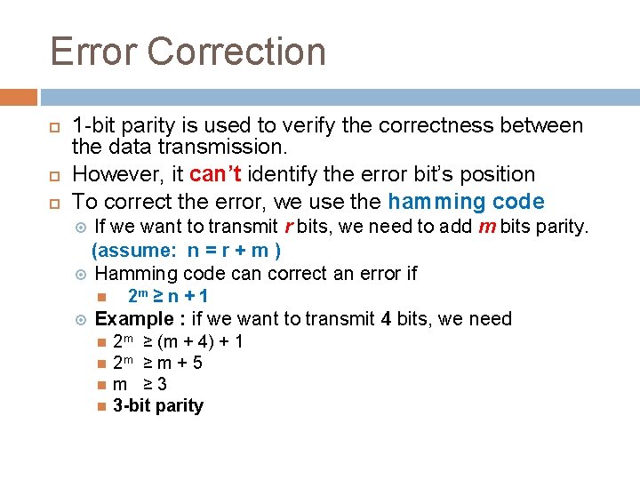
Error Correction 1 -bit parity is used to verify the correctness between the data transmission. However, it can’t identify the error bit’s position To correct the error, we use the hamming code If we want to transmit r bits, we need to add m bits parity. (assume: n = r + m ) Hamming code can correct an error if 2 m ≥ n + 1 Example : if we want to transmit 4 bits, we need 2 m ≥ (m + 4) + 1 2 m ≥ m + 5 m ≥ 3 3 -bit parity
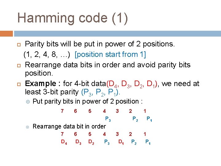
Hamming code (1) Parity bits will be put in power of 2 positions. (1, 2, 4, 8, …) [position start from 1] Rearrange data bits in order and avoid parity bits position. Example : for 4 -bit data(D 4, D 3, D 2, D 1), we need at least 3 -bit parity (P 3, P 2, P 1). Put parity bits in power of 2 position : 7 6 5 4 3 P 3 2 1 P 2 P 1 3 2 D 1 P 2 1 P 1 Rearrange data bit in order 7 D 4 6 D 3 5 D 2 4 P 3
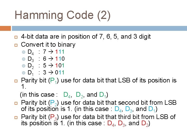
Hamming Code (2) 4 -bit data are in position of 7, 6, 5, and 3 digit Convert it to binary D 4 D 3 D 2 D 1 : : 7 111 6 110 5 101 3 011 Parity bit (P 1) use for data bit that LSB of its position is 1. (in this case : D 4, D 2, and D 1) Parity bit (P 2) use for data bit that second bit from LSB of its position is 1. (in this case : D 4, D 3, and D 1) Parity bit (P 3) use for data bit that third bit from LSB of its position is 1. (in this case : D 4, D 3, and D 2)
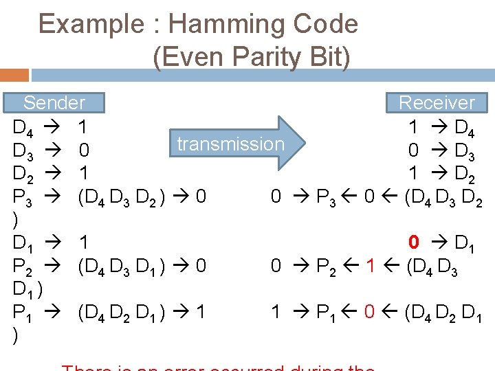
Example : Hamming Code (Even Parity Bit) Sender Receiver D 4 1 1 D 4 transmission D 3 0 0 D 3 D 2 1 1 D 2 P 3 (D 4 D 3 D 2 ) 0 0 P 3 0 (D 4 D 3 D 2 ) D 1 1 0 D 1 P 2 (D 4 D 3 D 1 ) 0 0 P 2 1 (D 4 D 3 D 1 ) P 1 (D 4 D 2 D 1 ) 1 1 P 1 0 (D 4 D 2 D 1 )
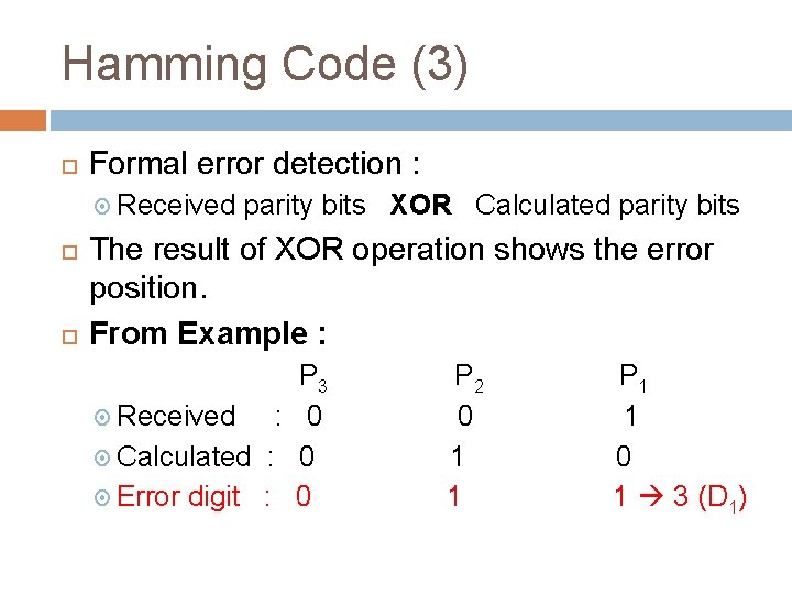
Hamming Code (3) Formal error detection : Received parity bits XOR Calculated parity bits The result of XOR operation shows the error position. From Example : P 3 Received : 0 Calculated : 0 Error digit : 0 P 2 0 1 1 P 1 1 0 1 3 (D 1)