EMT 1143 INTRODUCTION TO ELECTRIC CIRCUITS CHAPTER 3


 • Kirchhoff’s Voltage Laws (KVL) • Ohm’s Law")
 Sum of currents entering a node is zero Convention: +i")


 common ground (b) ground (c) chassis ground")


 Applying KCL to the supernode Eq: 1")
 Applying KVL to the supernode Eq: 2 Modify eq: 2 into eq: 1;")


- Slides: 28
EMT 114/3 INTRODUCTION TO ELECTRIC CIRCUITS CHAPTER 3: Circuit Analysis Method 3. 1 Node-voltage Method School of Microelectronic Engineering, Universiti Malaysia
Chapter 3 Outline q Node Voltage q Mesh Current q Source Transformation ØThevenin ØNorton ØPower School of Microelectronic Engineering, Universiti Malaysia
CIRCUITS ANALYSIS METHOD q Node Voltage q Mesh Current q Source Transformation ØThevenin ØNorton ØPower School of Microelectronic Engineering, Universiti Malaysia
RECALL • Kirchhoff’s Current Laws (KCL) • Kirchhoff’s Voltage Laws (KVL) • Ohm’s Law School of Microelectronic Engineering, Universiti Malaysia
KIRCHHOFF’S CURRENT LAW (KCL) Sum of currents entering a node is zero Convention: +i is entering, -i is leaving Or The summation of currents entering a node is equal to the summation of currents leaving the node Convention: +i is entering and leaving School of Microelectronic Engineering, Universiti Malaysia
Nodal Analysis n Nodal analysis provides a general procedure for analyzing circuits using node voltages as the circuits variables. n Choosing node voltages instead of element voltages as circuit variables is convenient and reduces the number of equations. School of Microelectronic Engineering, Universiti Malaysia
Nodal Analysis Step to determine the node voltages: 1. Choose a node as the reference node. 2. Select voltages v 1, v 2, …, vn-1 to the remaining n-1 nodes. The voltages are referenced with respect to the reference node. 3. Apply KCL to each of the n-1 non-reference nodes. Use Ohm’s law to express the branch currents in terms of node voltages. 4. Solve the resulting simultaneous equations to obtain the unknown node voltages. School of Microelectronic Engineering, Universiti Malaysia
Cont. . Symbol for reference node a) common ground (b) ground (c) chassis ground School of Microelectronic Engineering, Universiti Malaysia
3. 1 Motivation on Nodal Analysis If you are given the following circuit, how can we determine (1) the voltage across each resistor, (2) current through each resistor. (3) power generated by each current source, etc. What are things which we need to know in order to determine the answers?
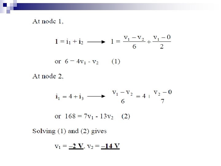
Example 1: Circuit with independent Current Source 3 In the diagram, node 3 is define as reference node and node 1 and 2 as node voltage labeled as; V 1 and V 2 Calculate the node voltages for above circuits. School of Microelectronic Engineering, Universiti Malaysia
At node 2, apply KCL eq : 2 At node 1, apply KCL Modify eq: 1 to eq: 2; eq : 1 School of Microelectronic Engineering, Universiti Malaysia
Example 2 3 1. How many nonreference node? 2. How many reference node? 3. Define node voltages School of Microelectronic Engineering, Universiti Malaysia
Nodal analysis with voltage dependant source If the circuit contains dependent sources, the nodevoltage equations must be supplemented with the constraint equation imposed by the presence of the dependent sources. School of Microelectronic Engineering, Universiti Malaysia
Example 3: Using nodal analysis, find V 0 in the circuit
3 i 1 v 1 i 3 5 i 2 + V 0 3 V 2 + – + 4 V 0 – – 1 i 1 + i 2 + i 3 = 0 Using Voltage divider so that v 1 + 5 v 1 - 15 + v 1 - or v 1 = 15 x 5/(27) = 2. 778 V, therefore vo = 2 v 1/5 = 1. 1111 V
Node analysis with SUPERNODE Case 1: Ø If voltage source is connected between reference node and a nonreference node, we set the voltage at the nonreference node equal to the voltage of the voltage source. Case 2: Ø If voltage source is connected between two nonreference node, the two nonreference nodes form a generalized node or SUPERNODE ; we apply both KCL and KVL to determine the node voltages
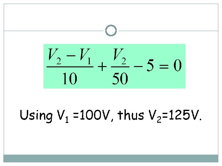
Example 4 CASE 1
Example 5 CASE 2 By applying the KCL and KCV, calculate the V 1 and V 2
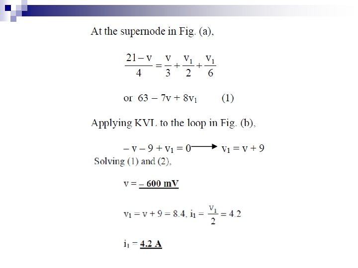
a) Applying KCL to the supernode Eq: 1
b) Applying KVL to the supernode Eq: 2 Modify eq: 2 into eq: 1;
Example 6
Exercise 1 Find V 1 and V 2?
Exercise 2 With voltage dependent source, find V 1 and V 2?
To be continued….