EGN 3373 Introduction to Electrical Systems I A
- Slides: 35
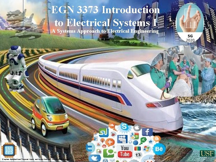
EGN 3373 Introduction to Electrical Systems I A Systems Approach to Electrical Engineering Graphics Adapted from “Physical, Earth, and Space Science”, Tom Hsu, cpo. Science.
Syllabus & Policies EGN 3373 -Section 002 Electrical Systems I Time/Place: MW 12: 30 -1: 45 EDU 115 Pre-requisites: PHY 2049, PHY 2049 L (Physics II and Lab) Co-requisites: MAP 2302 (Differential Equations) Textbook: Electrical Engineering: Concepts and Applications, Zekavat; ISBN: 1269527045, by Pearson. j. Course Coordinators: Dr. Sylvia Thomas Office Hours (instructor): TR 11: 00 AM – 12: 15 PM Office: ENB 368 Telephone: 813 -974 -4011 e-mail: sylvia@usf. edu Course Objectives: To study the fundamental principles and analysis techniques of electrical circuits: resistance, inductance, capacitance, dependent and independent sources, AC and DC circuits, transient and steady state analysis, operation and applications of basic electronic devices.
Syllabus & Policies EGN 3373 -Section 002 Electrical Systems I Course Objectives: To study the fundamental principles and analysis techniques of electrical circuits: resistance, inductance, capacitance, dependent and independent sources, AC and DC circuits, transient and steady state analysis, operation and applications of basic electronic devices. Topics: * Systems - * Signals – digital, analog, processing * Circuits – sources, elements, analysis * Electronics – diodes, op amps, transistors * Controls – transfer function, feedback * Electromagnetics – transmission, RF
WHY ELECTRICAL ENGINEERING (EE) ? • EE is the field of engineering that deals with the study of electricity, electronics, and electromagnetics (by controlling the flow of charges (or charged particles like electrons) and energy (in the form of electromagnetic waves)). • Studying EE will help prepare you as a technical leader for projects, increase your versatility and diversity as an engineer able to apply skills to practical problems, and enhance cross discipline communications. • The two key areas of EE deal with (a) energy/power generation, transmission, and consumption, and (b) information processing, storage, and transmission. • There is essentially no device/system/appliance we use in our daily lives that does not use electricity !!
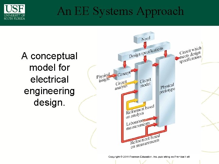
An EE Systems Approach A conceptual model for electrical engineering design.
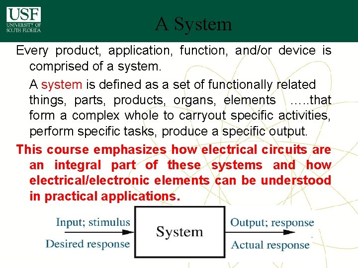
A System Every product, application, function, and/or device is comprised of a system. A system is defined as a set of functionally related things, parts, products, organs, elements …. . that form a complex whole to carryout specific activities, perform specific tasks, produce a specific output. This course emphasizes how electrical circuits are an integral part of these systems and how electrical/electronic elements can be understood in practical applications.
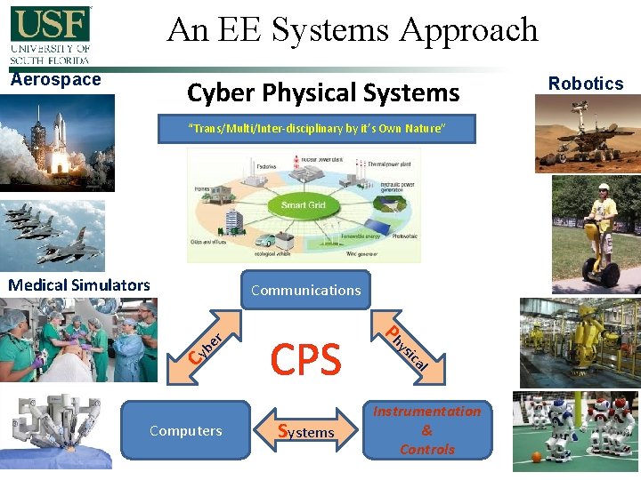
An EE Systems Approach Aerospace Cyber Physical Systems “Trans/Multi/Inter-disciplinary by it’s Own Nature” Medical Simulators Cy l ica Systems ys Computers CPS Ph be r Communications Instrumentation & Controls Robotics
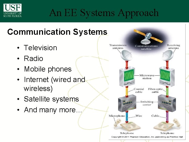
An EE Systems Approach Communication Systems • • Television Radio Mobile phones Internet (wired and wireless) • Satellite systems • And many more…
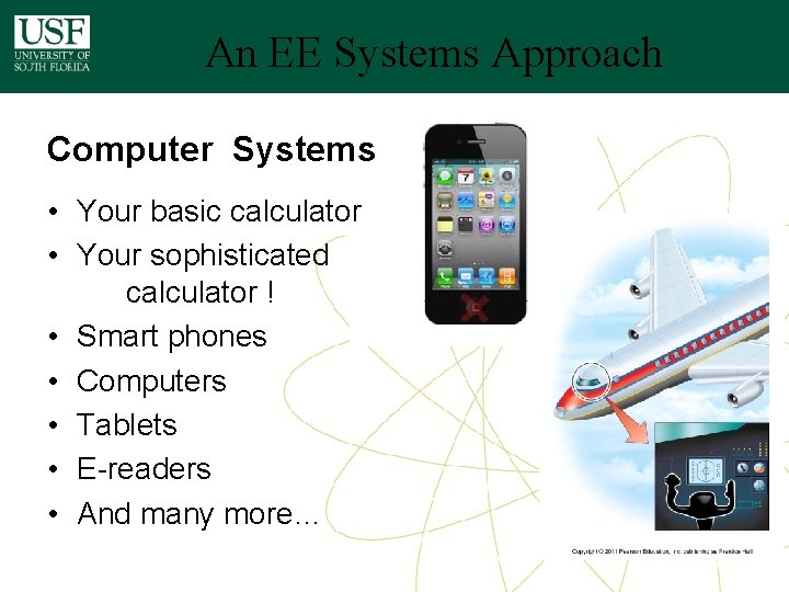
An EE Systems Approach Computer Systems • Your basic calculator • Your sophisticated calculator ! • Smart phones • Computers • Tablets • E-readers • And many more…
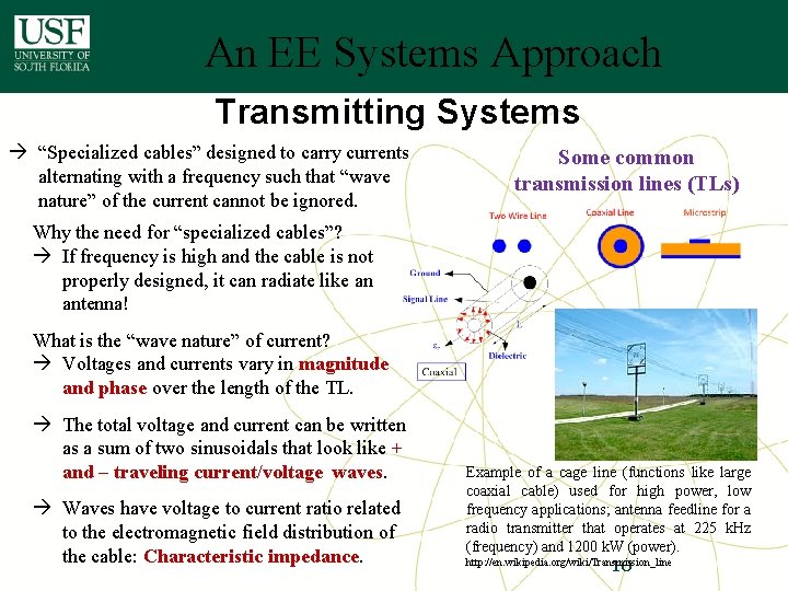
An EE Systems Approach Transmitting Systems à “Specialized cables” designed to carry currents alternating with a frequency such that “wave nature” of the current cannot be ignored. Some common transmission lines (TLs) Why the need for “specialized cables”? à If frequency is high and the cable is not properly designed, it can radiate like an antenna! What is the “wave nature” of current? à Voltages and currents vary in magnitude and phase over the length of the TL. à The total voltage and current can be written as a sum of two sinusoidals that look like + and – traveling current/voltage waves. à Waves have voltage to current ratio related to the electromagnetic field distribution of the cable: Characteristic impedance. Example of a cage line (functions like large coaxial cable) used for high power, low frequency applications; antenna feedline for a radio transmitter that operates at 225 k. Hz (frequency) and 1200 k. W (power). 10 http: //en. wikipedia. org/wiki/Transmission_line
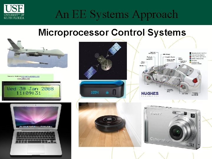
An EE Systems Approach Microprocessor Control Systems
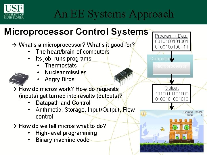
An EE Systems Approach Microprocessor Control Systems à What’s a microprocessor? What’s it good for? • The heart/brain of computers • Its job: runs programs • Thermostats • Nuclear missiles • Angry Birds à How do micros work? How do requests (inputs) get turned into results (outputs)? • Datapath and Control • Arithmetic, Storage, Input/Output, Flow control Program + Data 0010100100100111 Computer Microprocessor Output 1010010101000 01001010 à How do we tell micros what to do? • High-level programming • Binary machine code 12
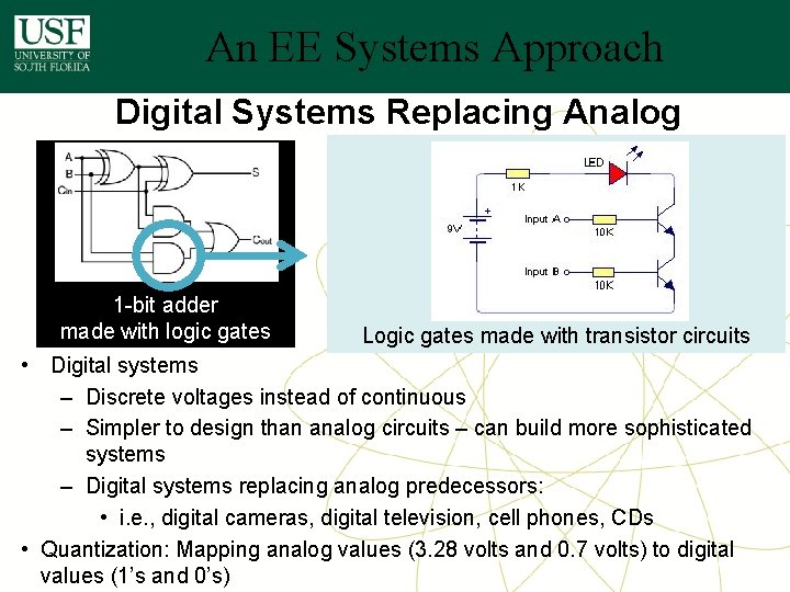
An EE Systems Approach Digital Systems Replacing Analog 1 -bit adder made with logic gates Logic gates made with transistor circuits • Digital systems – Discrete voltages instead of continuous – Simpler to design than analog circuits – can build more sophisticated systems – Digital systems replacing analog predecessors: • i. e. , digital cameras, digital television, cell phones, CDs • Quantization: Mapping analog values (3. 28 volts and 0. 7 volts) to digital values (1’s and 0’s)
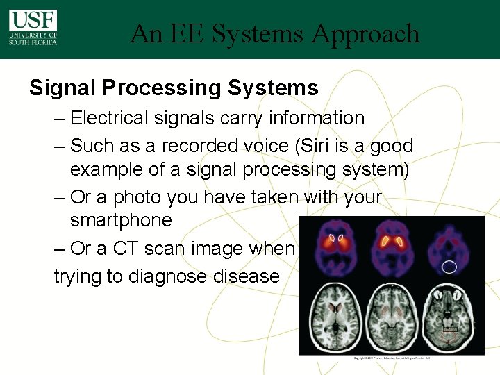
An EE Systems Approach Signal Processing Systems – Electrical signals carry information – Such as a recorded voice (Siri is a good example of a signal processing system) – Or a photo you have taken with your smartphone – Or a CT scan image when trying to diagnose disease
An EE Systems Approach Practical Applications of Systems – Similar to sample systems presented in Chapter 1
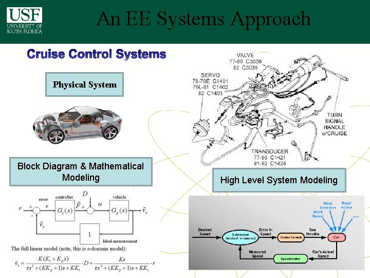
An EE Systems Approach Physical System Block Diagram & Mathematical Modeling High Level System Modeling
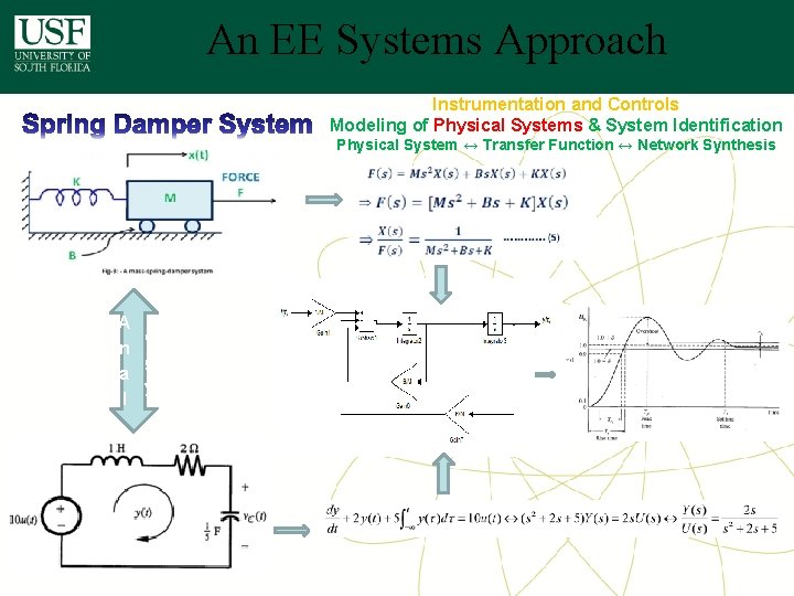
An EE Systems Approach Instrumentation and Controls Modeling of Physical Systems & System Identification Physical System ↔ Transfer Function ↔ Network Synthesis A o n g a y l
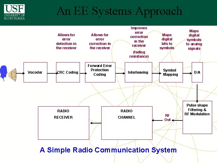
An EE Systems Approach Allows for error detection in the receiver Allows for error correction in the receiver Improves error correction in the receiver Maps digital bits to symbols (fading resistance) Vocoder CRC Coding Forward Error Protection Coding Interleaving RADIO RECEIVER CHANNEL Symbol Mapping RF Out A Simple Radio Communication System Maps digital symbols to analog signals D/A Pulse shape Filtering & RF Modulation
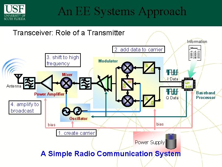
An EE Systems Approach Transceiver: Role of a Transmitter Information 2. add data to carrier 3. shift to high frequency Modulator A 0 90 u. P/ DSP A Q Data D Oscillator bias The lkhefw wlkhq wejklh wajkhrqwilu wilehr esjlkh qwh wlh wae. wklhjr qlih qilh q q 3 wih lihewrw wejklh wajkhrqwilu q esjlkh qwh wlh wae. lihewrw wklhjr qlih qilh q q 3 wih wejklh wajkhrqwilu q wae. esjlkh qwh wlh wklhjr qlih qilh q q 3 wih lihewrw q wklhjr qlih qilh q q 3 wih q wejklh wajkhrqwilu esjlkh qwh wlh wae. wklhjr qlih qilh q q 3 wih lihewrw wejklh wajkhrqwilu q esjlkh qwh wlh wae. wklhjr qlih qilh q q 3 wih lihewrw wklhjr qlih qilh q q 3 wih q wejklh wajkhrqwilu q wae. esjlkh qwh wlh wklhjr qlih qilh q q 3 wih lihewrw wejklh wajkhrqwilu q wae. I Data Power Amplifier 4. amplify to broadcast The lkhefw wlkhq wejklh wajkhrqwilu wilehr esjlkh qwh wlh wae. wklhjr qlih qilh q q 3 wih lihewrw wejklh wajkhrqwilu q esjlkh qwh wlh wae. lihewrw wklhjr qlih qilh q q 3 wih wejklh wajkhrqwilu q wae. esjlkh qwh wlh wklhjr qlih qilh q q 3 wih lihewrw wejklh wajkhrqwilu q esjlkh qwh wlh wae. lihewrw wklhjr qlih qilh q q 3 wih q wklhjr qlih qilh q q 3 wih wejklh wajkhrqwilu q esjlkh qwh wlh wae. wklhjr qlih qilh q q 3 wih lihewrw wejklh wajkhrqwilu q esjlkh qwh wlh wae. lihewrw wklhjr qlih qilh q q 3 wih q wejklh wajkhrqwilu q esjlkh qwh wlh wae. lihewrw D Mixer Antenna HPMX-2007 The lkhefw wlkhq wejklh wajkhrqwilu wilehr esjlkh qwh wlh wae. wklhjr qlih qilh q q 3 wih lihewrw wejklh wajkhrqwilu q wae. esjlkh qwh wlh wklhjr qlih qilh q q 3 wih lihewrw q wejklh wajkhrqwilu esjlkh qwh wlh wae. wklhjr qlih qilh q q 3 wih lihewrw wejklh wajkhrqwilu q esjlkh qwh wlh wae. wklhjr qlih qilh q q 3 wih lihewrw q wklhjr qlih qilh q q 3 wih wejklh wajkhrqwilu q esjlkh qwh wlh wae. wklhjr qlih qilh q q 3 wih lihewrw wejklh wajkhrqwilu q wae. esjlkh qwh wlh wklhjr qlih qilh q q 3 wih lihewrw q 1. create carrier Power Supply A Simple Radio Communication System Baseband Processor
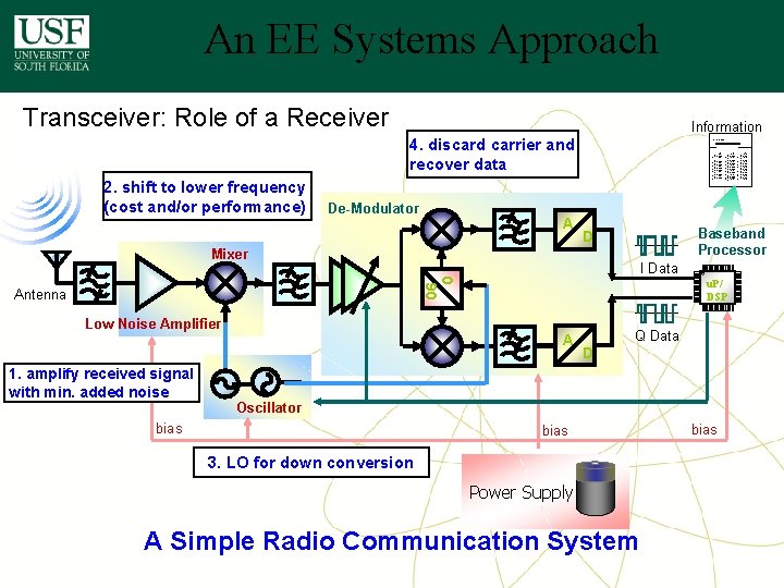
An EE Systems Approach Transceiver: Role of a Receiver Information 4. discard carrier and recover data 2. shift to lower frequency (cost and/or performance) De-Modulator A HPMX-2007 The lkhefw wlkhq wejklh wajkhrqwilu wilehr esjlkh qwh wlh wae. wklhjr qlih qilh q q 3 wih lihewrw wejklh wajkhrqwilu q wae. esjlkh qwh wlh wklhjr qlih qilh q q 3 wih lihewrw q wejklh wajkhrqwilu esjlkh qwh wlh wae. wklhjr qlih qilh q q 3 wih lihewrw wejklh wajkhrqwilu q esjlkh qwh wlh wae. wklhjr qlih qilh q q 3 wih lihewrw q wklhjr qlih qilh q q 3 wih wejklh wajkhrqwilu q esjlkh qwh wlh wae. wklhjr qlih qilh q q 3 wih lihewrw wejklh wajkhrqwilu q wae. esjlkh qwh wlh wklhjr qlih qilh q q 3 wih lihewrw q I Data 0 90 Low Noise Amplifier 1. amplify received signal with min. added noise u. P/ DSP A Q Data D Oscillator bias The lkhefw wlkhq wejklh wajkhrqwilu wilehr esjlkh qwh wlh wae. wklhjr qlih qilh q q 3 wih lihewrw wejklh wajkhrqwilu q esjlkh qwh wlh wae. lihewrw wklhjr qlih qilh q q 3 wih wejklh wajkhrqwilu q wae. esjlkh qwh wlh wklhjr qlih qilh q q 3 wih lihewrw q wklhjr qlih qilh q q 3 wih q wejklh wajkhrqwilu esjlkh qwh wlh wae. wklhjr qlih qilh q q 3 wih lihewrw wejklh wajkhrqwilu q esjlkh qwh wlh wae. wklhjr qlih qilh q q 3 wih lihewrw wklhjr qlih qilh q q 3 wih q wejklh wajkhrqwilu q wae. esjlkh qwh wlh wklhjr qlih qilh q q 3 wih lihewrw wejklh wajkhrqwilu q wae. Baseband Processor D Mixer Antenna The lkhefw wlkhq wejklh wajkhrqwilu wilehr esjlkh qwh wlh wae. wklhjr qlih qilh q q 3 wih lihewrw wejklh wajkhrqwilu q esjlkh qwh wlh wae. lihewrw wklhjr qlih qilh q q 3 wih wejklh wajkhrqwilu q wae. esjlkh qwh wlh wklhjr qlih qilh q q 3 wih lihewrw w q ejklh wajkhrqwilu esjlkh qwh wlh wae. lihewrw wklhjr qlih qilh q q 3 wih q wklhjr qlih qilh q q 3 wih wejklh wajkhrqwilu q esjlkh qwh wlh wae. wklhjr qlih qilh q q 3 wih lihewrw wejklh wajkhrqwilu q esjlkh qwh wlh wae. lihewrw wklhjr qlih qilh q q 3 wih w q klhjr qlih qilh q q 3 wih wejklh wajkhrqwilu q esjlkh qwh wlh wae. lihewrw bias 3. LO for down conversion Power Supply A Simple Radio Communication System bias
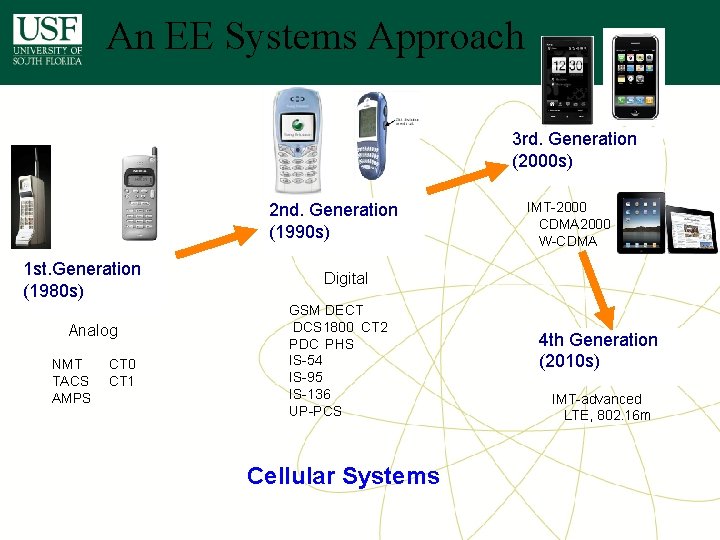
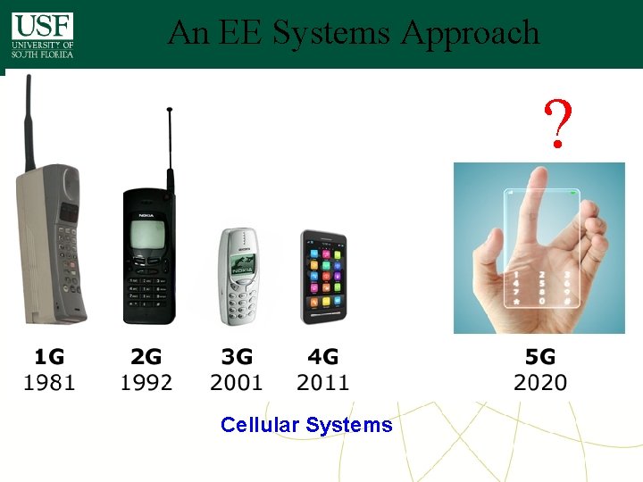
An EE Systems Approach 3 rd. Generation (2000 s) 2 nd. Generation (1990 s) 1 st. Generation (1980 s) Analog NMT CT 0 TACS CT 1 AMPS IMT-2000 CDMA 2000 W-CDMA Digital GSM DECT DCS 1800 CT 2 PDC PHS IS-54 IS-95 IS-136 UP-PCS Cellular Systems 4 th Generation (2010 s) IMT-advanced LTE, 802. 16 m
An EE Systems Approach ? Cellular Systems
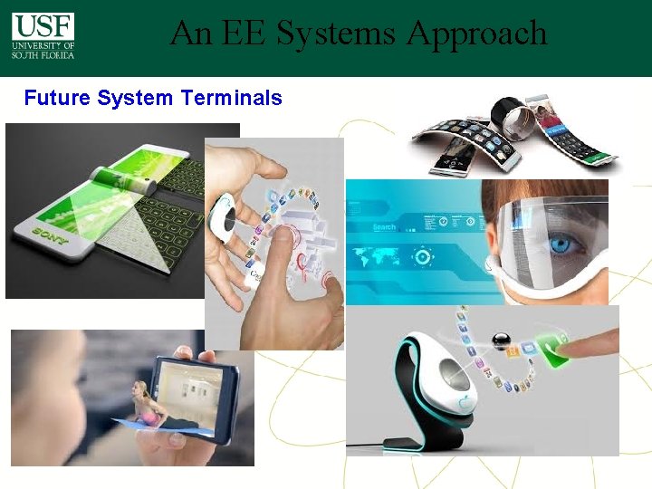
An EE Systems Approach Future System Terminals
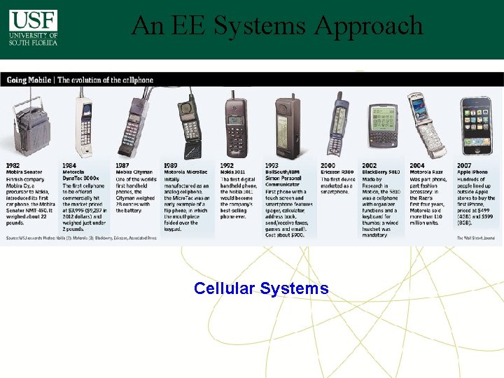
An EE Systems Approach Cellular Systems
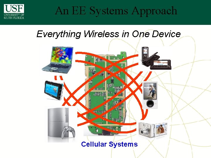
An EE Systems Approach Everything Wireless in One Device Cellular Systems
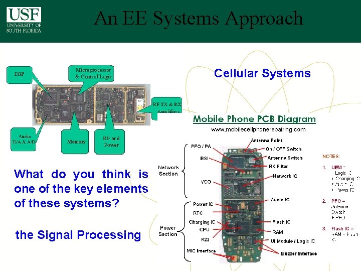
An EE Systems Approach Cellular Systems What do you think is one of the key elements of these systems? the Signal Processing EE-6593
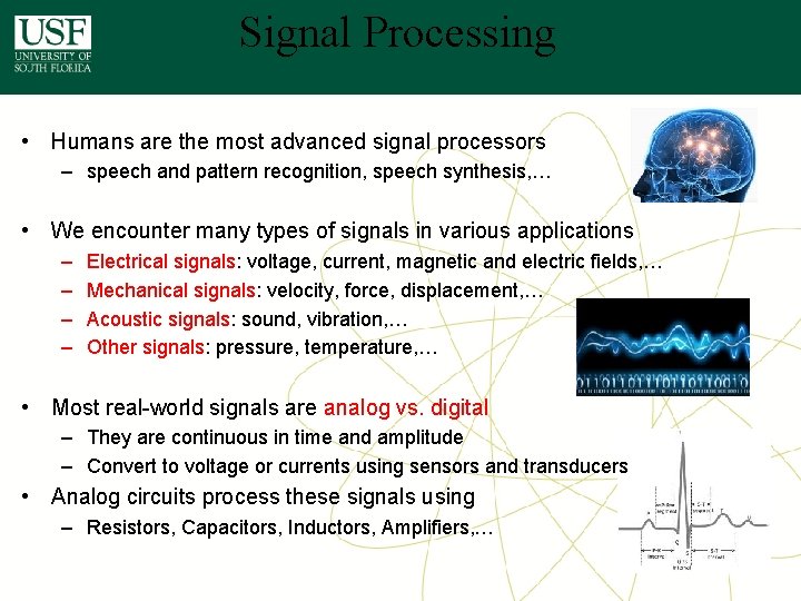
Signal Processing • Humans are the most advanced signal processors – speech and pattern recognition, speech synthesis, … • We encounter many types of signals in various applications – – Electrical signals: voltage, current, magnetic and electric fields, … Mechanical signals: velocity, force, displacement, … Acoustic signals: sound, vibration, … Other signals: pressure, temperature, … • Most real-world signals are analog vs. digital – They are continuous in time and amplitude – Convert to voltage or currents using sensors and transducers • Analog circuits process these signals using – Resistors, Capacitors, Inductors, Amplifiers, …
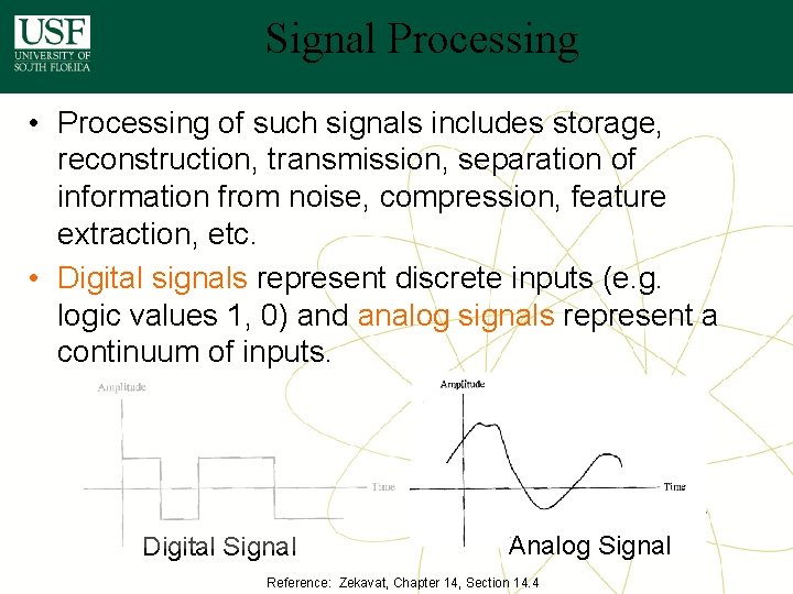
Signal Processing • Processing of such signals includes storage, reconstruction, transmission, separation of information from noise, compression, feature extraction, etc. • Digital signals represent discrete inputs (e. g. logic values 1, 0) and analog signals represent a continuum of inputs. Digital Signal Analog Signal Reference: Zekavat, Chapter 14, Section 14. 4
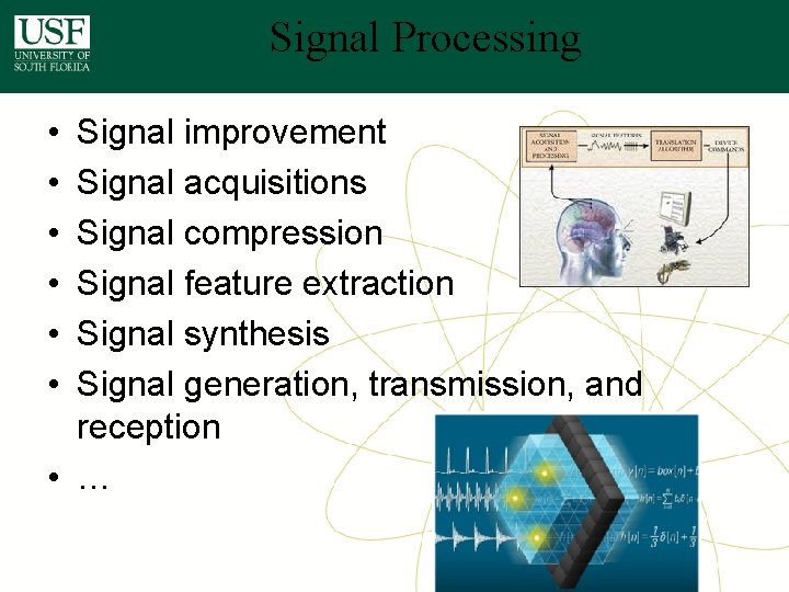
Signal Processing • • • Signal improvement Signal acquisitions Signal compression Signal feature extraction Signal synthesis Signal generation, transmission, and reception • …
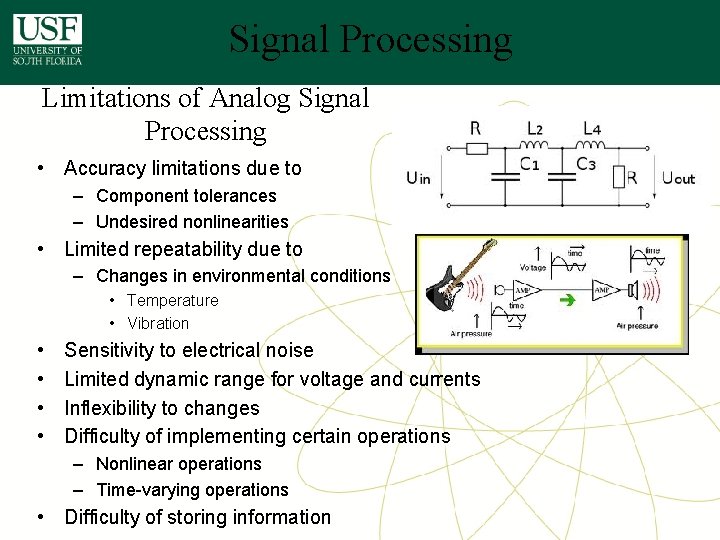
Signal Processing Limitations of Analog Signal Processing • Accuracy limitations due to – Component tolerances – Undesired nonlinearities • Limited repeatability due to – Changes in environmental conditions • Temperature • Vibration • • Sensitivity to electrical noise Limited dynamic range for voltage and currents Inflexibility to changes Difficulty of implementing certain operations – Nonlinear operations – Time-varying operations • Difficulty of storing information
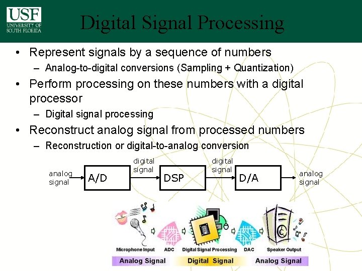
Digital Signal Processing • Represent signals by a sequence of numbers – Analog-to-digital conversions (Sampling + Quantization) • Perform processing on these numbers with a digital processor – Digital signal processing • Reconstruct analog signal from processed numbers – Reconstruction or digital-to-analog conversion analog signal A/D digital signal DSP digital signal D/A analog signal
DSP is Everywhere • Sound applications – Compression, enhancement, special effects, synthesis, recognition, echo cancellation, … – Cell Phones, MP 3 Players, Movies, Dictation, Text-to-speech, … • Communication – Modulation, coding, detection, equalization, echo cancellation, … – Cell Phones, dial-up modem, DSL modem, Satellite Receiver, … • Automotive – ABS, GPS, Active Noise Cancellation, Cruise Control, Parking, … • Medical – Magnetic Resonance, Tomography, Electrocardiogram, … • Military – Radar, Sonar, Space photographs, remote sensing, … • Image and Video Applications – DVD, JPEG, Movie special effects, video conferencing, … • Mechanical – Motor control, process control, oil and mineral prospecting, …
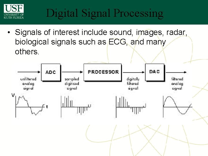
Digital Signal Processing • Signals of interest include sound, images, radar, biological signals such as ECG, and many others.
Digital Signal Processing • A series of trigonometric and arithmetic operations. • Series of steps called “algorithms” • Digital Processing – a series of instructions to manipulate the digital numbers. • Algorithm classes – Spectral analysis – Digital filtering – Coding and compressing data – Noise reduction – Etc.
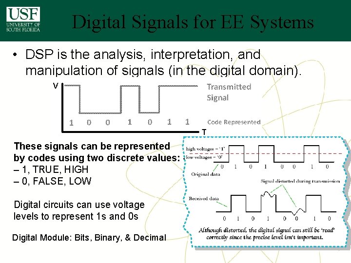
Digital Signals for EE Systems • DSP is the analysis, interpretation, and manipulation of signals (in the digital domain). These signals can be represented by codes using two discrete values: – 1’s and 0’s – 1, TRUE, HIGH – 0, FALSE, LOW Digital circuits can use voltage levels to represent 1 s and 0 s Digital Module: Bits, Binary, & Decimal