EAT 456 FOUNDATION ENGINEERIG SOIL IMPROVEMENT AND GROUND


 O Objectives: O Reduce the settlement for structures. O Improve shear")


")
 O Step 1 O The jet at the bottom of the")
 O Step 2 O The water jet creates a quick condition")
 O Step 3 O Granular material is poured into the top")
 O Step 4 O The vibrating unit is gradually raised in")
 O The success of densification of in situ soil depends on")
 O The range of the grain-size distribution of in situ soil")


")
")
")


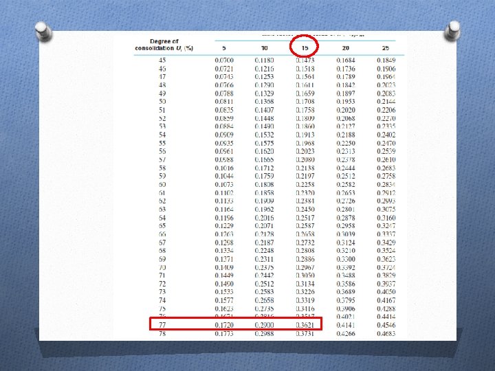
 According to Figure 14. 19, for Tv = 0. 36, the")
 O Given; O ∆σ’(p) O σ’ 0 = 115 k. N/m")
 According to Figure 14. 17, for U = 47% and ∆σ’(p)")

 O The soil inside the pile is then jetted out,")
")
")
")
")


 O")
 O")
 O According to Figure 14. 17, for ∆σ’(p) / σ’ 0")

 O A surcharge is applied as shown in figure below.")

 From figure, UV ≈ 9%")
 O")
 O")
 O The total primary settlement is thus And the settlement after")


")
 O After stone columns are constructed, a fill material should")


 O Lime stabilization in the field can be done in")

 O For field compaction, the proper amount of cement can")


 O Single Rod System O A cement slurry is injected")
 O Double Rod System O The cement slurry is injected")
 O Triple Rod System O Uses high-pressure water shielded in")

 O They are constructed by driving a hollow mandrel")

- Slides: 61
EAT 456 FOUNDATION ENGINEERIG SOIL IMPROVEMENT AND GROUND MODIFICATION ILYA BT JOOHARI
TOPICS O General principles of compaction O Field compaction O Vibroflotation O Blasting O Precompression O Sand drains
INTRODUCTION O Soil at the site may not always be totally suitable for supporting structures. O Granular soil deposits; in situ soil may be very loose and indicate a large elastic settlement – soil need to be densified to increase its unit weight an thus its shear strength. O Top layers of the soil are undesirable and must be removed and replaced with better soil – soil used as fill should be well compacted to sustained the desired structural load. O Soft saturated clay layers – improving in situ soils by using additives (stabilization)
INTRODUCTION (CONT. ) O Objectives: O Reduce the settlement for structures. O Improve shear strength of soil and increase the bearing capacity of shallow foundations. O Increase the FOS against possible slope failures of embankment and earth dams. O Reduce shrinkage and swelling of soils.
GENERAL PRINCIPLES OF COMPACTION O If small amount of water is added to a soil that is then compacted – certain unit weight. O If the moisture content of the same soil is gradually increased and energy of compaction is the same – dry unit weight gradually increase. O Water acts as a lubricant between soil particles – rearrange the solid particles. O Standard laboratory tests used to evaluate maximum dry unit weights and optimum moisture contents.
FIELD COMPACTION O Ordinary compaction in the field is done by rollers. Most common: O Smooth – wheel rollers O Pneumatic rubber – tired rollers O Sheepsfoot rollers O Vibratory rollers
VIBROFLOTATION O Developed in Germany in the 1930 s for in – situ densification of thick layers of loosed granular soil deposits. O Process involves the use of a vibroflot (called the vibrating unit). The device is 2 m length. Vibrating unit has an eccentric weight inside it and can develop a centrifugal force. Openings at the bottom and top of the unit are for water jets. O The entire compaction process can be divided into four steps.
VIBROFLOTATION (CONT. )
VIBROFLOTATION (CONT. ) O Step 1 O The jet at the bottom of the vobroflot is turned on, and the vibroflot is lowered into the ground.
VIBROFLOTATION (CONT. ) O Step 2 O The water jet creates a quick condition in the soil, which allows the vibrating unit to sink.
VIBROFLOTATION (CONT. ) O Step 3 O Granular material is poured into the top of the hole. The water from the lower jet is transferred to the jet at the top of the vibrating unit. This water carries the granular material down the hole.
VIBROFLOTATION (CONT. ) O Step 4 O The vibrating unit is gradually raised in about 0. 3 m lifts and is held vibrating for about 30 seconds at a time. This process compacts the soil to the desired unit weight.
VIBROFLOTATION (CONT. ) O The success of densification of in situ soil depends on several factors, the most important of which are the grain-size distribution of the soil and the nature of the backfill used to fill the holes during the withdrawal period of the vibroflot.
VIBROFLOTATION (CONT. ) O The range of the grain-size distribution of in situ soil marked Zone 1 is most suitable for compaction by vibroflotation. Soils that contain excessive amounts of fine sand silt-size particles are difficult to compact; for such soils, considerable effort is needed to reach the proper relative density of compaction. O Zone 2 is the approximate lower limit of grain-size distribution for compaction by vibroflotation. O Soil deposits whose grain-size distribution falls into Zone 3 contain appreciable amounts of gravel. For these soils, the rate of probe penetration may be rather slow, so compaction by vibroflotation might prove to be uneconomical in the long run.
BLASTING O Densification of granular soils. O Involves the detonation of explosive charges such as 60% dynamite at a certain depth below the ground surface in saturated soil. O 3 to 5 successful detonations are usually necessary to achieve the desired compaction. O Compaction up to a depth of about 18 m over a large area can easily be achieved by using this process. O Explosive charges are placed at the depth of about two – thirds of the thickness of the soil layer desired to be compacted.
PRECOMPRESSION O When highly compressible, normally consolidated clayey soil layers lie at a limited depth and large consolidation settlements are expected as result of large buildings construction, precompression of soil may be used to minimize post construction settlement.
PRECOMPRESSION (CONT. )
PRECOMPRESSION (CONT. )
PRECOMPRESSION (CONT. )
EXAMPLE O During the construction of a highway bridge, the average permanent load on the clay layer is expected to increase by 115 k. N/m 2. The average effective overburden pressure at the middle of the clay is 210 k. N/m 2 . The clay is normally consolidated. Determine the surcharge, ∆σ’(f) needed to eliminate the entire primary consolidation settlement in 9 months by precompression. Use Hc = 6 m, Cc = 0. 28, e 0 = 0. 9, and Cv = 0. 36 m 2/mo.
SOLUTION O Cv = 0. 36 m 2/mo O H O t 2 O Tv = 3 m (two – way drainage) = 9 months = (0. 36)(9)/32 = 0. 36
SOLUTION (CONT. ) According to Figure 14. 19, for Tv = 0. 36, the value of U is 47%
SOLUTION (CONT. ) O Given; O ∆σ’(p) O σ’ 0 = 115 k. N/m 2 = 210 k. N/m 2 O ∆σ’(p) / σ’ 0 = 115 / 210 = 0. 548
SOLUTION (CONT. ) According to Figure 14. 17, for U = 47% and ∆σ’(p) / σ’ 0 = 0. 548 ∆σ’(f) / ∆σ’(p) ≈ 1. 8, thus ∆σ’(f) = (1. 8)(115) = 207 k. N/m 2
SAND DRAINS O Accelerate the consolidation settlement of soft, normally consolidated clay layers and achieve precompression before the construction of a desired foundation. O Drilling holes through clay layers in the field at regular intervals. Holes are then backfilled with sand. O Several methods; O Rotary drilling and then backfilling with sand O Drilling by continuous – flight auger with a hollow stem and backfilling with sand O Driving hollow sheet piles
SAND DRAINS (CONT. ) O The soil inside the pile is then jetted out, after which the backfilling with sand is done. Then, surcharge is applied at the ground surface. O Surcharge will increase pore water pressure in clay. Excess pore water pressure – dissipated by drainage (vertically and radially). O Average degree of consolidation due to radial drainage only and vertical drainage only.
SAND DRAINS (CONT. )
SAND DRAINS (CONT. )
SAND DRAINS (CONT. )
SAND DRAINS (CONT. )
EXAMPLE 1 O From previous example, recalculate with addition of some sand drains. Assume rw = 0. 1 m, de = 3 m, Cv = Cvr , and the surcharge is applied instantaneously. Assume no – smear case.
SOLUTION O
SOLUTION (CONT. ) O
SOLUTION (CONT. ) O
SOLUTION (CONT. ) O According to Figure 14. 17, for ∆σ’(p) / σ’ 0 = 0. 548 and Uvr = 92. 4% O ∆σ’(f) / ∆σ’(p) ≈ 0. 12, thus O ∆σ’(f) = (0. 12)(115) = 13. 8 k. N/m 2
EXAMPLE 2 Suppose that, for the sand drain project, the clay is normally consolidated. Given the following data: Clay: Hc = 4. 57 m (two-way drainage) Cc = 0. 31 eo = 1. 1 Effective overburden pressure at the middle of the clay layer = 47. 92 k. N/m 2 Cv = 106. 15 x 10 -4 m 2/day Sand drain: rw = 0. 091 m de = 1. 83 m Cv = Cvr
EXAMPLE 2 (CONT. ) O A surcharge is applied as shown in figure below. Assume this to be a no-smear case. Calculate the degree of consolidation 30 days after the surcharge is first applied. Also, determine the consolidation settlement at that time due to the surcharge.
SOLUTION O
SOLUTION (CONT. ) From figure, UV ≈ 9%
SOLUTION (CONT. ) O
SOLUTION (CONT. ) O
SOLUTION (CONT. ) O The total primary settlement is thus And the settlement after 30 days is
Part 2
TOPICS O Stone columns O Stabilization by admixtures O Jet grouting O Sand compaction piles
STONE COLUMS O Generally consists of water-jetting a vibroflot into the soft clay layer to make a circular hole that extends through the clay to firmer soil. O The hole is then filled with an imported gravel. O The gravel in the hole is gradually compacted as the vibrator is withdrawn. O The gravel used for the stone column has a size range of 6 to 40 mm. Stone columns usually have diameters of 0. 5 to 0. 75 m and are spaced at about 1. 5 to 3 m center to center.
STONE COLUMS (CONT. )
STONE COLUMS (CONT. ) O After stone columns are constructed, a fill material should always be placed over the ground surface and compacted before the foundation is constructed. O Stone columns work more effectively when they are used to stabilize a large area where the undrained shear strength of the subsoil is in the range of 10 to 50 k. N/m 2 than to improve the bearing capacity of structural foundations
STABILIZATION BY ADMIXTURES O Admixtures are occasionally used to stabilize soils in the field — particularly fine-grained soils. O The most common admixtures are lime, cement, and lime– fly ash. O The main purposes of stabilizing the soil are to (a) modify the soil (b) expedite construction (c) improve the strength and durability of the soil
LIME STABILIZATION O The quantity of lime used to stabilize most soils usually is in the range from 5 to 10%. O When lime is added to clayey soils, the clay particles tend to clump together to form larger particles, thereby a) decreasing the liquid limit b) increasing the plastic limit c) decreasing the plasticity index d) increasing the shrinkage limit e) increasing the workability f) improving the strength and deformation properties of a soil.
LIME STABILIZATION (CONT. ) O Lime stabilization in the field can be done in three ways. They are 1. The in situ material or the borrowed material can be mixed with the proper amount of lime at the site and then compacted after the addition of moisture. 2. The soil can be mixed with the proper amount of lime and water at a plant and then hauled back to the site for compaction. 3. Lime slurry can be pressure injected into the soil to a depth of 4 to 5 m.
CEMENT STABILIZATION O Cement is being increasingly used as a stabilizing material for soil, particularly in the construction of highways and earth dams. O Cement can be used to stabilize sandy and clayey soils. O As in the case of lime, cement helps decrease the liquid limit and increase the plasticity index and workability of clayey soils. O Granular soils and clayey soils with low plasticity obviously are most suitable for cement stabilization.
CEMENT STABILIZATION (CONT. ) O For field compaction, the proper amount of cement can be mixed with soil either at the site or at a mixing plant. O If the latter approach is adopted, the mixture can then be carried to the site. O The soil is compacted to the required unit weight with a predetermined amount of water.
FLY ASH STABILIZATION O Fly ash is pozzolanic in nature and can react with hydrated lime to produce cementitious products. O For that reason, lime–fly-ash mixtures can be used to stabilize highway bases and subbases. O Effective mixes can be prepared with 10 to 35% fly ash and 2 to 10% lime. O Soil–lime–fly-ash mixes are compacted under controlled conditions, with proper amounts of moisture to obtain stabilized soil layers.
JET GROUTING O A soil stabilization process whereby cement slurry in injected into soil at a high velocity to form a soil–concrete matrix. O Conceptually, the process of jet grouting was first developed in the 1960 s. O The effectiveness of the jet grouting is very much influenced by the nature of erodibility of soil. O Gravelly soil and clean sand are highly erodible, whereas highly plastic clays are difficult to erode. O Three basic systems of jet grouting have been developed—single, double, and triple rod systems.
JET GROUTING (CONT. ) O Single Rod System O A cement slurry is injected at a high velocity to form a soil–cement matrix
JET GROUTING (CONT. ) O Double Rod System O The cement slurry is injected at a high velocity sheathed in a cone of air at an equally high velocity to erode and mix the soil well.
JET GROUTING (CONT. ) O Triple Rod System O Uses high-pressure water shielded in a cone of air to erode the soil. O The void created in this process is then filled with a pre-engineering cement slurry.
SAND COMPACTION PILES O Can be used in marginal sites to improve stability, control liquefaction, and reduce the settlement of various structures. O Built in soft clay, these piles can significantly accelerate the pore water pressure-dissipation process and hence the time for consolidation.
SAND COMPACTION PILES (CONT. ) O They are constructed by driving a hollow mandrel with its bottom closed during driving. O On partial withdrawal of the mandrel, the bottom doors open. O Sand is poured from the top of the mandrel and is compacted in steps by applying air pressure as the mandrel is withdrawn. O The piles are usually 0. 46 to 0. 76 m in diameter and are placed at about 1. 5 to 3 m center to center. O The pattern of layout of sand compaction piles is the same as for stone columns.
END