Dr Vaishali D Khairnar Terna Engineering College Nerul


")


; Ipv 4 Address.")


; Ipv 4 Address. Helper address; address. Set.")


; Ipv 4 Address. Helper address; address. Set.")


; Application. Container server. Apps = udp.")

")


; Internet. Stack. Helper")

; } Running the Script “Simple. NS 3 Simulation 2. cc”")


- Slides: 41
Dr. Vaishali D. Khairnar Terna Engineering College, Nerul, Navi-Mumbai
Installation of NS-3 � Install ubuntu 14. 04 � Install some packages ◦ $ sudo apt-get update ◦ $ sudo apt-get install gcc g++ python-dev mercurial bzr gdb valgrind gsl-bin libgsl 0 -dev libgsl 0 ldbl flex bison tcpdump sqlite 3 libsqlite 3 -dev libxml 2 -dev libgtk 2. 0 -0 libgtk 2. 0 -dev uncrustify doxygen graphviz imagemagick python-pygraphviz python-kiwi python-pygoocanvas libgoocanvas-dev pythonpygccxml (All these package will take 27 MB)
Download NS 3 ◦ Link (https: //www. nsnam. org/release/ns-allinone 3. 25. tar. bz 2) extract it (Preferably your home directory)and write command…… $ cd ns-allinone-3. 25 (4 folders under the folder ns-allinone-3. 25 ◦ ◦ ns 3. 21 netanim-3. 107 bake pybindgen-0. 17. 0. post 49+ng 0 e 4 e 3 bc)
�$ chmod +x build. py � $. /build. py –enable-examples –enable-tests � If all is ok, you will get this message “Build finished successfully”. � write command => � $ cd ns-3. 21 � $. /waf -d debug –enable-examples –enable-tests configure � $. /waf � $make configure (make script which will indirectly build ns 3 using waf) � $make
� To check everything is successfully installed or not, please run this command � $. /test. py � Installation is finished. � Now how you can run the programs of these folder – ns-allinone-3. 21/ns-3. 21/example ? � copy first. cc from the example folder and then put it on ns-allinone-3. 21/ns-3. 21/scratch folder. � write command => � $. /waf –run first � You will see this output � At time 3 s client sent 1024 bytes to 10. 1. 1. 2 port 9 At time 3. 00469 s server received 1024 bytes from 10. 1. 1. 1 port 49153 At time 3. 00469 s server sent 1024 bytes to 10. 1. 1. 1 port 49153 At time 3. 00837 s client received 1024 bytes from 10. 1. 1. 2 port 9
Installing the Network Animation tool “Netanim” � � � � � $cd ns-allinone-3. 25/netanim-3. 107 $make clean $qmake Net. Anim. pro $make Now we may use the netanim tool for visualizing our network simulations. Testing Net. Anim with a given example simulation. $cd ns-allinone-3. 25 $. /waf –run dumbbell-animation Waf: Entering directory `/home/yourhome/ns-allinone-3. 25/ns 3. 25/build’ Waf: Leaving directory `/home/yourhome/ns-allinone-3. 25/ns 3. 25/build’ Build commands will be stored in build/compile_commands. json ‘build’ finished successfully (1. 536 s) Animation Trace file created: dumbbell-animation. xml (Since we run the simulation from the folder ns-allinone-3. 25, it will create the output file “dumbbell-animation. xml” inside that folder. )
If you already set the path variable “Net. Anim”, then you can start Net. Anim from that folder itself $ Net. Anim It will show the empty Net. Anim window.
� Now, open the “dumbbell-animation. xml” file by pressing the folder at the top left of the toolbar. � Now you can visualize the simulation by pressing the green play button.
Simple Simulation From “Scratch” (simple point to point network scenario)
Simulation Basics Simulation time moves in discrete jumps from event to event C++ functions schedule events to occur at specific simulation times A simulation scheduler orders the event execution Simulation: : Run() gets it all started Simulation stops at specific time or when events end
Example - conceptual
Example – ns 3 implemented Protocol Stack
Example Script - 1 /* Simple. NS 3 Simulation 1. cc */ #include #include "ns 3/core-module. h" "ns 3/network-module. h" "ns 3/internet-module. h" "ns 3/point-to-point-module. h" "ns 3/applications-module. h" include modules that will be used using namespace ns 3; ns-3 project namespace enable and disable console message logging by reference to the name //NS_LOG_COMPONENT_DEFINE ("First. Script. Example"); int main (int argc, char *argv[]) { //Log. Component. Enable ("Udp. Echo. Client. Application", LOG_LEVEL_INFO); //Log. Component. Enable ("Udp. Echo. Server. Application", LOG_LEVEL_INFO); Node. Container nodes; nodes. Create (2); Point. To. Point. Helper point. To. Point; point. To. Point. Set. Device. Attribute ("Data. Rate", String. Value ("5 Mbps")); point. To. Point. Set. Channel. Attribute ("Delay", String. Value ("2 ms")); Net. Device. Container devices; devices = point. To. Point. Install (nodes); Topology Configuration
Example Script - 2 Internet. Stack. Helper stack; stack. Install (nodes); Ipv 4 Address. Helper address; address. Set. Base (“ 192. 168. 1. 0", "255. 0"); Set up internet stack Ipv 4 Interface. Container interfaces = address. Assign (devices); Udp. Echo. Server. Helper echo. Server (9); Application. Container server. Apps = echo. Server. Install (nodes. Get (1)); server. Apps. Start (Seconds (1. 0)); server. Apps. Stop (Seconds (10. 0)); Udp. Echo. Client. Helper echo. Client (interfaces. Get. Address (1), 9); echo. Client. Set. Attribute ("Max. Packets", Uinteger. Value (1)); echo. Client. Set. Attribute ("Interval", Time. Value (Seconds (1. 0))); echo. Client. Set. Attribute ("Packet. Size", Uinteger. Value (1024)); Application. Container client. Apps = echo. Client. Install (nodes. Get (0)); client. Apps. Start (Seconds (2. 0)); client. Apps. Stop (Seconds (10. 0)); Run the simulation Simulator: : Run (); Simulator: : Destroy (); return 0; } Set up applications
Running Example ALL SCENARIOS SHOULD BE RUN UNDER SCRATCH Change to the directory “ns-3. 25” ◦ $ cd ns-allinone 3. 25/ns-3. 25/ ◦ And run the simulation ◦ $ waf -–run Simple. NS 3 Simulation 1 After running the simulation, you will not see any interesting output; because didn’t enable any log components in the script. Your terminal window may just show the following :
Enabling Log components can be enabled by adding few lines in the simulation script or by simply setting appropriate environment variables in the command prompt itself. In this example, we are going to enable the log components by adding few lines in the simulation script. By doing in this way, we can actually understand the message logging facility available in ns-3.
Enabling Log components /* Simple. NS 3 Simulation 1. cc */ #include #include "ns 3/core-module. h" "ns 3/network-module. h" "ns 3/internet-module. h" "ns 3/point-to-point-module. h" "ns 3/applications-module. h" include modules that will be used using namespace ns 3; NS_LOG_COMPONENT_DEFINE ("First. Script. Example"); ns-3 project namespace enable and disable console message logging by reference to the name int main (int argc, char *argv[]) { Log. Component. Enable ("Udp. Echo. Client. Application", LOG_LEVEL_INFO); // Log. Component. Enable ("Udp. Echo. Server. Application", LOG_LEVEL_INFO); Node. Container nodes; nodes. Create (2); Point. To. Point. Helper point. To. Point; point. To. Point. Set. Device. Attribute ("Data. Rate", String. Value ("5 Mbps")); point. To. Point. Set. Channel. Attribute ("Delay", String. Value ("2 ms")); Net. Device. Container devices; devices = point. To. Point. Install (nodes); Topology Configuration
Internet. Stack. Helper stack; stack. Install (nodes); Ipv 4 Address. Helper address; address. Set. Base (“ 192. 168. 1. 0", "255. 0"); Set up internet stack Ipv 4 Interface. Container interfaces = address. Assign (devices); Udp. Echo. Server. Helper echo. Server (9); Application. Container server. Apps = echo. Server. Install (nodes. Get (1)); server. Apps. Start (Seconds (1. 0)); server. Apps. Stop (Seconds (10. 0)); Udp. Echo. Client. Helper echo. Client (interfaces. Get. Address (1), 9); echo. Client. Set. Attribute ("Max. Packets", Uinteger. Value (1)); echo. Client. Set. Attribute ("Interval", Time. Value (Seconds (1. 0))); echo. Client. Set. Attribute ("Packet. Size", Uinteger. Value (1024)); Application. Container client. Apps = echo. Client. Install (nodes. Get (0)); client. Apps. Start (Seconds (2. 0)); client. Apps. Stop (Seconds (10. 0)); Run the simulation Simulator: : Run (); Simulator: : Destroy (); return 0; } Set up applications
Other way In this example, we are going to enable the log components by setting appropriate environment variables. By doing in this way, we can actually understand the message logging facility available in ns-3.
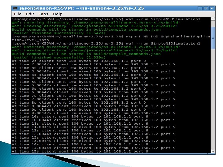
If we set the environment variable NS_LOG as follows, $ export NS_LOG=Udp. Echo. Client. Application=level_info Run the simulation again $ waf –run Simple. NS 3 Simulation 1 Now it will start to display the info log of Udp. Echo. Client. Application.
If you see the output, then you may see only the “sending” and “receiving” events of the Udp. Echo. Client. Application. It will show events up to around 100 seconds. Because we are only using default attributes of the Udp. Echo. Client. Application so that it will send 1 echo requests for each second and send 100 requests in total (the default values).
If you want to see the log info events belongs to the Udp. Echo. Server. Application
Enabling Log components /* Simple. NS 3 Simulation 1. cc */ #include #include "ns 3/core-module. h" "ns 3/network-module. h" "ns 3/internet-module. h" "ns 3/point-to-point-module. h" "ns 3/applications-module. h" include modules that will be used using namespace ns 3; NS_LOG_COMPONENT_DEFINE ("First. Script. Example"); ns-3 project namespace enable and disable console message logging by reference to the name int main (int argc, char *argv[]) { Log. Component. Enable ("Udp. Echo. Client. Application", LOG_LEVEL_INFO); Log. Component. Enable ("Udp. Echo. Server. Application", LOG_LEVEL_INFO); Node. Container nodes; nodes. Create (2); Point. To. Point. Helper point. To. Point; point. To. Point. Set. Device. Attribute ("Data. Rate", String. Value ("5 Mbps")); point. To. Point. Set. Channel. Attribute ("Delay", String. Value ("2 ms")); Net. Device. Container devices; devices = point. To. Point. Install (nodes); Topology Configuration
Internet. Stack. Helper stack; stack. Install (nodes); Ipv 4 Address. Helper address; address. Set. Base (“ 192. 168. 1. 0", "255. 0"); Set up internet stack Ipv 4 Interface. Container interfaces = address. Assign (devices); Udp. Echo. Server. Helper echo. Server (9); Application. Container server. Apps = echo. Server. Install (nodes. Get (1)); server. Apps. Start (Seconds (1. 0)); server. Apps. Stop (Seconds (10. 0)); Udp. Echo. Client. Helper echo. Client (interfaces. Get. Address (1), 9); echo. Client. Set. Attribute ("Max. Packets", Uinteger. Value (1)); echo. Client. Set. Attribute ("Interval", Time. Value (Seconds (1. 0))); echo. Client. Set. Attribute ("Packet. Size", Uinteger. Value (1024)); Application. Container client. Apps = echo. Client. Install (nodes. Get (0)); client. Apps. Start (Seconds (2. 0)); client. Apps. Stop (Seconds (10. 0)); Run the simulation Simulator: : Run (); Simulator: : Destroy (); return 0; } Set up applications
OR set the environment variable NS_LOG as follows: $ export NS_LOG=Udp. Echo. Client. Application=level_info: Udp. Echo. Server. Application=level_info run the simulation again $ waf –run Simple. NS 3 Simulation 1 Now it will start to display the info log of Udp. Echo. Client. Application as well as the info log of Udp. Echo. Server. Application. logs are used to trace errors while developing a simulation.
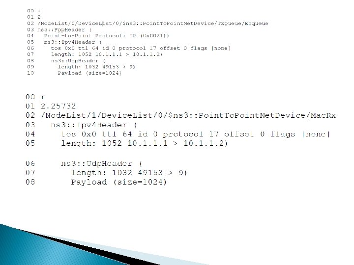
Trace Files For Analysis ns-3 provides one way to log events for further analysis of a network simulation. Other way is to “event trace files” similar to that of a ns-2 simulation. ns-3’s Ascii Trace file is some what similar to ns-2’s trace file. But the format of ns-3’s Ascii Trace is entirely different from that of ns -2.
Simple. NS 3 Simulation 3. cc #include “ns 3/core-module. h” #include “ns 3/network-module. h” #include “ns 3/point-to-point-module. h” #include “ns 3/internet-module. h” #include “ns 3/applications-module. h”using namespace ns 3; int main (int argc, char *argv[]) { Node. Container nodes; nodes. Create (2); Point. To. Point. Helper channel; channel. Set. Device. Attribute (“Data. Rate”, String. Value (“ 5 Mbps”)); channel. Set. Channel. Attribute (“Delay”, String. Value (“ 2 ms”)); Net. Device. Container net. Devices; net. Devices = channel. Install (nodes); Internet. Stack. Helper ip. Stack; ip. Stack. Install (nodes); Ipv 4 Address. Helper ip. Addresses; ip. Addresses. Set. Base (“ 192. 168. 1. 0”, “ 255. 0”); Ipv 4 Interface. Container ipinterfaces = ip. Addresses. Assign (net. Devices);
Udp. Echo. Server. Helper udp. Echo. Server (9); Application. Container server. Apps = udp. Echo. Server. Install (nodes. Get (1)); server. Apps. Start (Seconds (1. 0)); Udp. Echo. Client. Helper udp. Echo. Client (ipinterfaces. Get. Address (1), 9); Application. Container client. Apps = udp. Echo. Client. Install (nodes. Get (0)); client. Apps. Start (Seconds (2. 0)); Ascii. Trace. Helper event. Traces; channel. Enable. Ascii. All(event. Traces. Create. File. Stream(“Si mple. NS 3 Simulation_Event. Trace. Output. tr”)); Simulator: : Run (); }
Change to the directory “ns-3. 25” $ cd ns-allinone-3. 25/ns-3. 25/ Run the simulation $ waf –run Simple. NS 3 Simulation 3 After running the simulation, a Ascii trace file will be generated in the name “Simple. NS 3 Simulation_Event. Trace. Output. tr”
Visualizing ns-3 Simulation using Net. Anim (Net. Anim – An Animator for ns-3 Simulations)
Net. Anim is an offline network animator tool which is used through with ns-allinone-3. xx package. It can animate the ns-3 network simulation using an XML trace file that is generated as an output during simulation. So, the necessary steps for creating this XML trace file and setting its related attributes has to be done in the ns-3 simulation code itself.
Simple. NS 3 Simulation 2. cc #include “ns 3/core-module. h” #include “ns 3/network-module. h” #include “ns 3/point-to-point-module. h” #include “ns 3/internet-module. h” #include “ns 3/applications-module. h” #include “ns 3/mobility-module. h” #include “ns 3/netanim-module. h” using namespace ns 3; int main (int argc, char *argv[]) { Node. Container nodes; nodes. Create (2); Point. To. Point. Helper channel; channel. Set. Device. Attribute (“Data. Rate”, String. Value (“ 5 Mbps”)); channel. Set. Channel. Attribute (“Delay”, String. Value (“ 2 ms”));
Net. Device. Container net. Devices; net. Devices = channel. Install (nodes); Internet. Stack. Helper ip. Stack; ip. Stack. Install (nodes); Ipv 4 Address. Helper ip. Addresses; ip. Addresses. Set. Base (“ 192. 168. 1. 0”, “ 255. 0”); Ipv 4 Interface. Container ipinterfaces = ip. Addresses. Assign (net. Devices); Udp. Echo. Server. Helper udp. Echo. Server (9); Application. Container server. Apps = udp. Echo. Server. Install (nodes. Get (1)); server. Apps. Start (Seconds (1. 0)); Udp. Echo. Client. Helper udp. Echo. Client (ipinterfaces. Get. Address (1), 9); Application. Container client. Apps = udp. Echo. Client. Install (nodes. Get (0)); client. Apps. Start (Seconds (2. 0));
Mobility. Helper mobility; mobility. Set. Position. Allocator (“ns 3: : Grid. Position. Allocator”, “Min. X”, Double. Value (0. 0), “Min. Y”, Double. Value (0. 0), ”Delta. X”, Double. Value (5. 0), “Delta. Y”, Double. Value (10. 0), “Grid. Width”, Uinteger. Value (5), “Layout. Type”, String. Value (“Row. First”)); mobility. Set. Mobility. Model (“ns 3: : Constant. Position. Mobility. Model”); mobility. Install (nodes); Animation. Interface anim (“Simple. NS 3 Simulation_Net. Animation. Output. xml”); anim. Set. Constant. Position (nodes. Get(0), 0, 5); anim. Set. Constant. Position (nodes. Get(1), 10, 5);
Simulator: : Run (); } Running the Script “Simple. NS 3 Simulation 2. cc” Change to the directory “ns-3. 25” $ cd ns-allinone-3. 25/ns-3. 25/ Run the simulation $ waf –run Simple. NS 3 Simulation 2 After running the simulation, a XML trace file will be generated in the name “Simple. NS 3 Simulation_Net. Animation. Output. xml”
� run the Net. Anim � $Net. Anim � open a blank Net. Anim User Interface with a blank window
open the “Simple. NS 3 Simulation_Net. Animation. Output. xml” file using the lefttop folder icon on the tool-bar. Show the nodes at positions that are set in the simulation script.
Customizing the Visual Output in Net. Anim double-clicking on a node will open a property editor from which we can set some basic display property of a node
output shows the same network scenario after updating node display attributes.