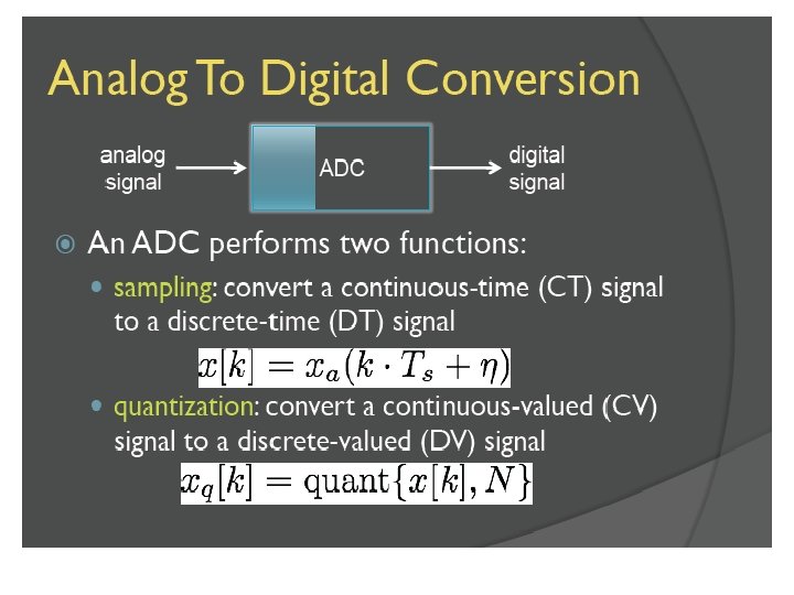
Digitization AD and DA Conversion Digital Processing w


 w Quantization error")


- Slides: 21
Digitization - A/D and D/A Conversion
Digital Processing w w w The two analog filters are used to avoid aliasing at the input and to smooth the output. They both have analog input and output The digital processor has a digital input and a digital output The ADC and DAC are hybrid devices : w The ADC has analog input and digital output w The DAC has digital input and analog output
Amplitude Sampling 2 1. 8 1. 6 1. 4 1. 2 1 0. 8 0. 6 0. 4 0. 2 0 w Take snapshots of continuously changing data w The Sampling Period is fixed w This makes information understandable 1 2 3 4 5 6 7 8 9 10 11 12 13 14 TIME (in Seconds) Sampling Period – The period between samples Sampling Time (The Snapshot) – The time taken to take a sample
Amplitude Missing Information – Improper Sampling 1. 4 1. 2 1 0. 8 0. 6 0. 4 0. 2 0 w Non-periodic sampling PBUY May miss information The dip between T 3 and T 4 goes unnoticed TIME T 1 T 2 Amplitude w T 3 T 4 T 5 T 6 1. 4 1. 2 1 0. 8 0. 6 0. 4 0. 2 0 w Information cannot be interpreted easily w Periodic sampling PBUY w May miss information The dip between T 2 and T 3 goes unnoticed TIME T 1 T 2 T 3 Actual variation Inferred plot T 4 w Easier to interpret The key is the sampling frequency.
Getting the Sampling Right TIME FREQUENCY |A| fs- fa fs+ fa |A| CASE 1 t fs>>fa fs = Sampling Frequency fa = Signal Frequency |A| CASE 2 t fa fs 2 fs f |A| fs=2 fa fa fs 2 fs f |A| t CASE 3 Inferred Signal fs<2 fa fs Alias Original Signal fa f
Aliasing due to Improper Sampling w Top: the analog signal and spectrum w Middle: Sampling, if done properly, allows error-free reconstruction of the analog signal from its samples w Bottom: if sampling rate is lower than twice the largest frequency in the signal, aliasing occurs.
Limiting the Spectrum |A| fs fm fs f w Frequency components greater than ½fs cause aliasing (f>fm) w Get rid of (filter out) frequencies above fm (no aliasing) w Then ensure that the sampling rate is greater than 2 fm Aliasing |A| fs>2 fm fm f
Quantizing the Signal |A| sample & ts 4 ts hold t 8 ts |A| w Aim is to limit the representation of each sample to a finite set of values – to quantize each sample w The set of quantization levels is the values representable in the digital processor w More levels means more accuracy, and smaller rounding error 11 10 01 00 ts |A| 4 ts 8 ts quantize ? ? ? t 11 10 01 Signal = 10 10 01 01 00 00 01 00 ts 4 ts 8 ts t
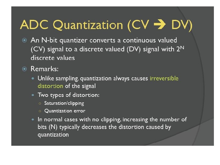
Digitizing the Signal w Digitization has two stages: of sampling and quantization w Sampling, if done properly, may be error-free w Quantization entails an error of half LSB ( ) w The distribution of quantization error is assumed uniform
Quantization Error |A| w Quantization introduces errors Quantization Error w Increasing the number of t |A| quantization levels is not always the answer to reducing error w Non-uniform Quantization w Use more levels where there are more variations w Use fewer levels where there are t fewer variations
Quantization Error w Quantization error for a sinusoidal signal (in blue) w Quantization error for an audio signal (in blue)
A Short reminder on Digitization Errors w Niquist sampling theorem states that we can sample a w w signal without losing information if we sample at twice the highest frequency in the signal Real A/D converters introduce quantization noise. This noise is commonly of uniform distribution, and is white - spreading throughout the frequency range. The quantization noise is reduced at about 6 d. B per bit w -48 d. B @ 8 bit w -72 d. B @ 12 bit w -96 d. B @ 16 bit
Types of A/D Converters w There are several types of A/D converters. Among the main ones are: w The fast Flash ADC w The slow Successive Approximation ADC w Pipelined ADC w The Sigma-Delta ADC
Smoothing the Output DAC 010001 DIGITAL IN LOWPASS FILTER SAMPLE AND HOLD |A| SMOOTHED OUTPUT |A| t t w Convert digital input to analog value w Hold until the next digital input is converted w Finally, smooth the output signal
Commercial Converters AIC 23 ANALOG IN ANALOG OUT ANTIALIASING FILTER RECONSTRUCTION FILTER ADC DAC SERIAL PORT Analog Interface Circuit (AIC) SERIAL DIGITAL OUT w ADC and DAC on same chip (Sigma Delta) w 16 bit digitized data serialized (ADC & DAC) w Interfaces to serial port of DSP w Programmable Antialiasing filter w Programmable Reconstruction filter (Smoothing Filter)
C 6713 DSK Design USB PC w w CTRL D 0–D 31 A 0–A 31 SERIAL PORT TMS 320 C 6713 AIC 23 ’C 6713, 32 -Bit Floating Point DSP w w 4 K x 32 Bits On-Chip Data Cache 128 K x 32 Bits On-Chip L 2 Cache 6 ns Single-Cycle Instruction Execution Time Analog Interface Unit (AIC) Contains w w w ADC (16 -bit) DAC (16 -bit) Filters w Parallel Port w JTAG and Expansion Connector ANALOG OUT ANALOG IN