
Voice Digitization Prepared By Engr Mohammad Tareq Assistant
Voice Digitization Prepared By: Engr. Mohammad Tareq Assistant Professor, Dept. of EETE
Contents • • Voice Digitization Process Pulse Amplitude Modulation (PAM( Quantization Companding Delta Modulation Differential Pulse Code Modulation (DPCM( 1/5/2022 2
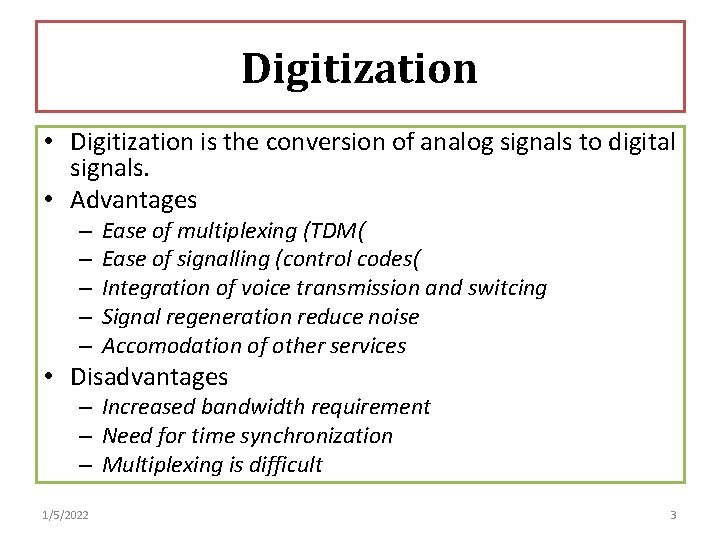
Digitization • Digitization is the conversion of analog signals to digital signals. • Advantages – – – Ease of multiplexing (TDM( Ease of signalling (control codes( Integration of voice transmission and switcing Signal regeneration reduce noise Accomodation of other services • Disadvantages – Increased bandwidth requirement – Need for time synchronization – Multiplexing is difficult 1/5/2022 3
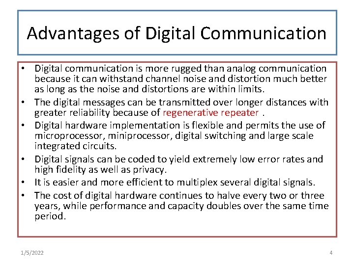
Advantages of Digital Communication • Digital communication is more rugged than analog communication because it can withstand channel noise and distortion much better as long as the noise and distortions are within limits. • The digital messages can be transmitted over longer distances with greater reliability because of regenerative repeater. • Digital hardware implementation is flexible and permits the use of microprocessor, miniprocessor, digital switching and large scale integrated circuits. • Digital signals can be coded to yield extremely low error rates and high fidelity as well as privacy. • It is easier and more efficient to multiplex several digital signals. • The cost of digital hardware continues to halve every two or three years, while performance and capacity doubles over the same time period. 1/5/2022 4
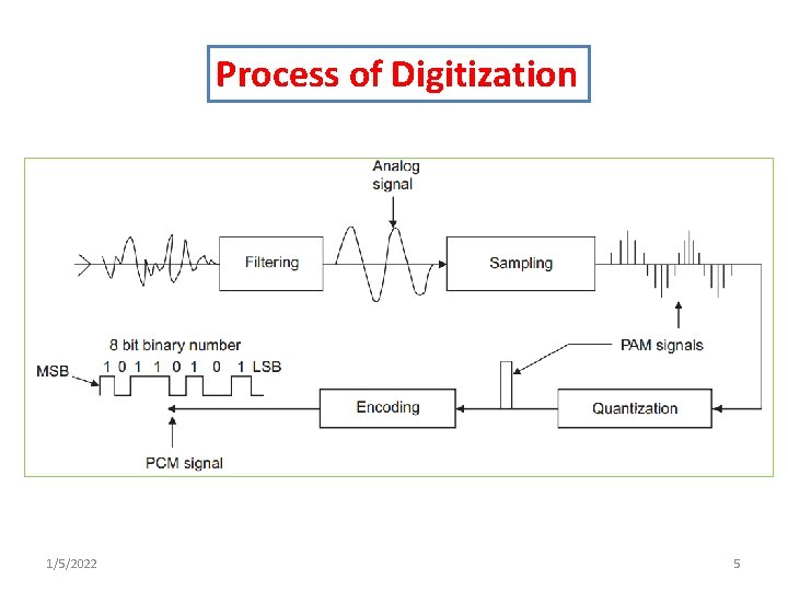
Process of Digitization 1/5/2022 5
Filtering • Frequencies below 300 Hz and above 3400 Hz (voice frequency range) are filtered from analog signal. • Thus the actual bandwidth of the filtered signal is 3100 Hz. 1/5/2022 6
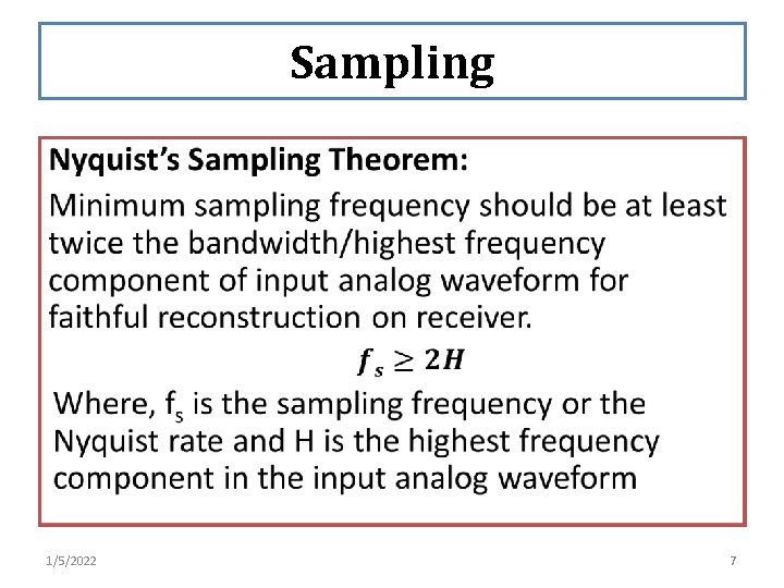
Sampling • 1/5/2022 7
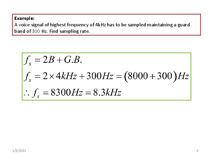
Example: A voice signal of highest frequency of 4 k. Hz has to be sampled maintaining a guard band of 300 Hz. Find sampling rate. 1/5/2022 8
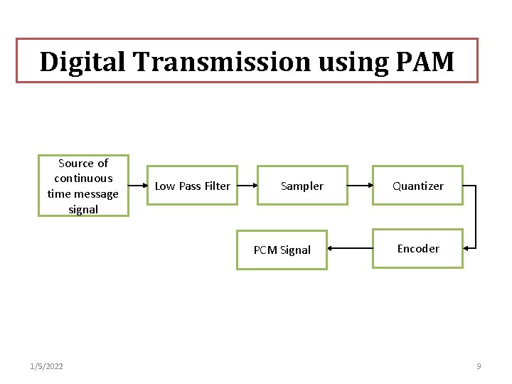
Digital Transmission using PAM Source of continuous time message signal Low Pass Filter Sampler PCM Signal 1/5/2022 Quantizer Encoder 9
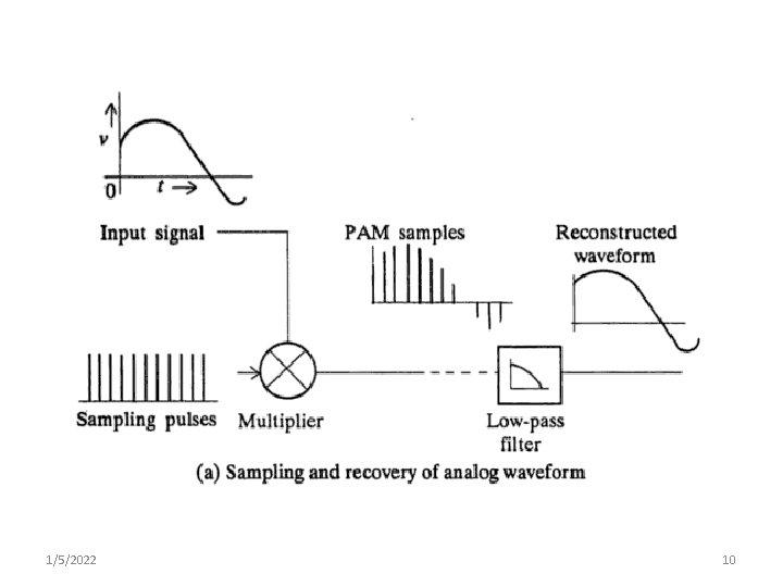
1/5/2022 10
1/5/2022 11
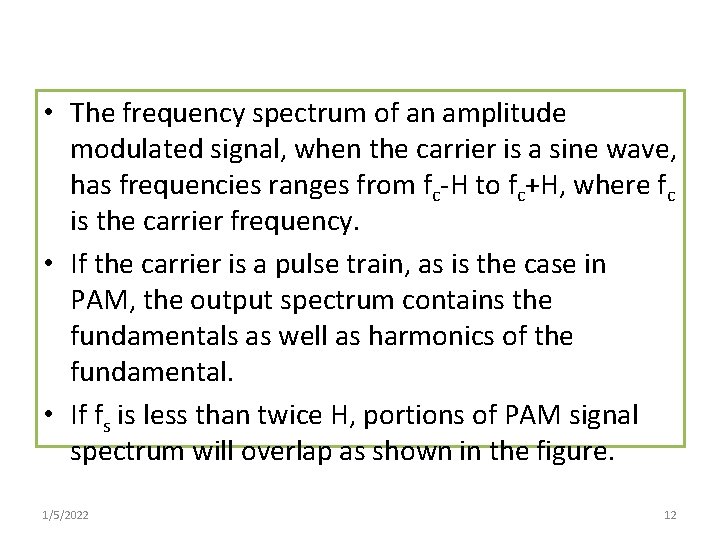
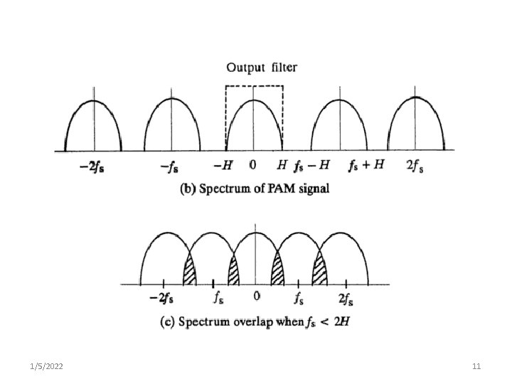
• The frequency spectrum of an amplitude modulated signal, when the carrier is a sine wave, has frequencies ranges from fc-H to fc+H, where fc is the carrier frequency. • If the carrier is a pulse train, as is the case in PAM, the output spectrum contains the fundamentals as well as harmonics of the fundamental. • If fs is less than twice H, portions of PAM signal spectrum will overlap as shown in the figure. 1/5/2022 12
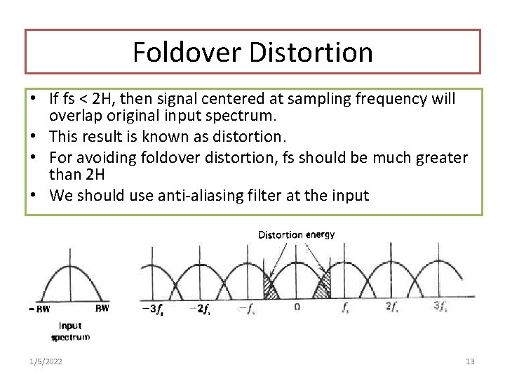
Foldover Distortion • If fs < 2 H, then signal centered at sampling frequency will overlap original input spectrum. • This result is known as distortion. • For avoiding foldover distortion, fs should be much greater than 2 H • We should use anti-aliasing filter at the input 1/5/2022 13
• Guard Band (GB): To support ideal characteristics of low pass filter we use guard band. • A narrow frequency band provided between adjacent channel is certain portions of the radio spectrum to prevent interference between stations is known as guard band. 1/5/2022 14
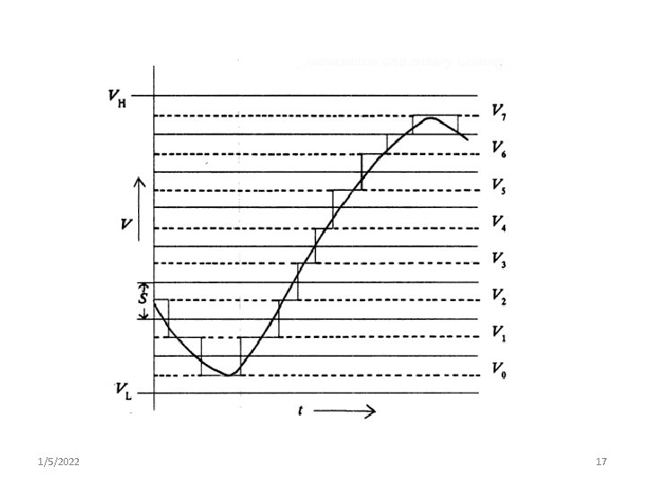
Quantization • Pulse Amplitude Modulated (PAM) samples are vulnerable to noise. • Infinite number of bits will be required for coding non-quantized PAM samples. • It is therefore necessary to quantize the PAM sample amplitude to the nearest of a range of discrete amplitude level. 1/5/2022 15
• 1/5/2022 16
1/5/2022 17
• Each quantized level is represented by a code number which is transmitted instead of the quantized sample value itself. • If binary arithmetic is used for coding, then the code number is transmitted as a series of pulses. • Hence, such a system of transmission is called Pulse Code Modulation (PCM). 1/5/2022 18
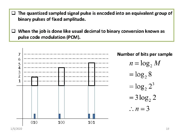
q The quantized sampled signal pulse is encoded into an equivalent group of binary pulses of fixed amplitude. q When the job is done like usual decimal to binary conversion known as pulse code modulation (PCM). Number of bits per sample 7 6 5 4 3 2 1 010 1/5/2022 100 101 19
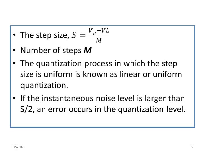
Process of Quantization • Let the sampled signal at the transmitter be quantized into total M discrete levels (uniform) with level spacing ‘a’ or ‘S’. • The quantization is done with maximum excursion positively or negatively. 1/5/2022 20
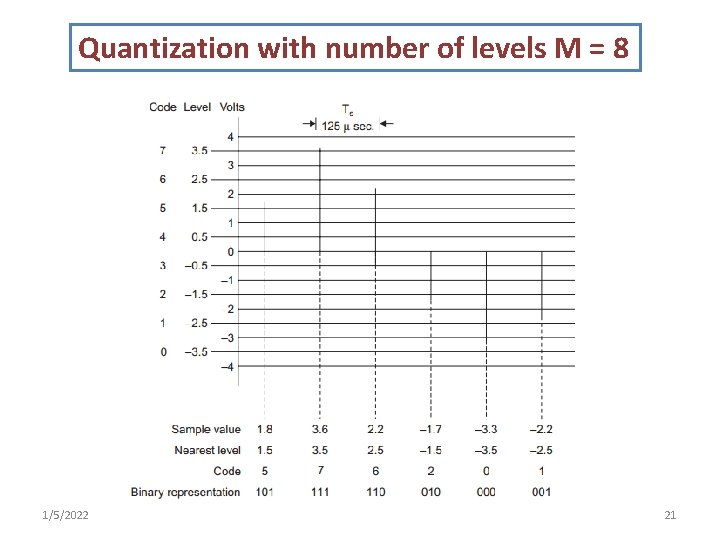
Quantization with number of levels M = 8 1/5/2022 21
• Let the signal m(t) is to be quantized. • Identify the signal excursion (negative peak to positive peak) which is ranges from VL to VH. • Divide the total range into M equal intervals. • In the center of each of these steps, we locate quantization levels. • If the sampled amplitude is in a particular interval, the nearest value is chosen and the corresponding binary digit is approximated as equivalent to the sampled amplitude. • The quality of the approximation may be improved by reducing the size of the steps, thereby increasing the number of allowable levels. 1/5/2022 22
• In the fourth step of the digitization process, the quantized samples are encoded into a digital bit stream (series of electrical pulses). • In practical system, 256 levels can be used to obtain quality of signal. • This results in the output of the encoding as 8 bit number. • This binary number (or 8 bit word) is transmitted over the network as a series of electrical or optical pulses. 1/5/2022 23
• In the case of 256 (0 to 255) levels, the digital encoder recognizes the 255 different voltage levels of the quantized samples. • Converts each into a string of eight bits (1 s and 0 s). • The series of pulses is called a digital bit stream. • The PCM process require a 64 kbps channel to encode a 4 k. Hz audio input signal because 8000 samples/sec × 8 bit/words = 64000 bps 1/5/2022 24
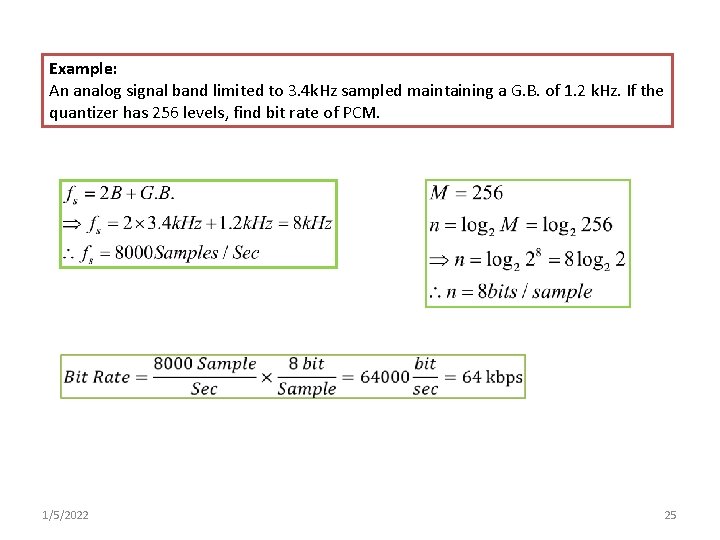
Example: An analog signal band limited to 3. 4 k. Hz sampled maintaining a G. B. of 1. 2 k. Hz. If the quantizer has 256 levels, find bit rate of PCM. 1/5/2022 25
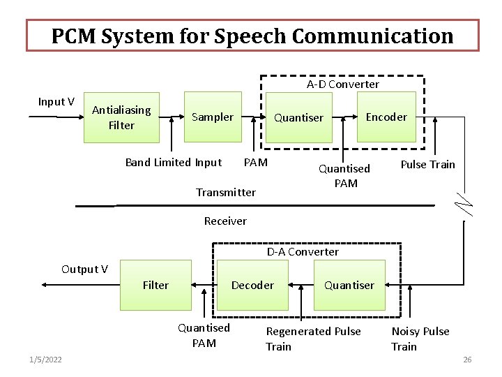
PCM System for Speech Communication A-D Converter Input V Antialiasing Filter Sampler Band Limited Input Encoder Quantiser PAM Transmitter Quantised PAM Pulse Train Receiver D-A Converter Output V Filter Decoder Quantised PAM 1/5/2022 Quantiser Regenerated Pulse Train Noisy Pulse Train 26
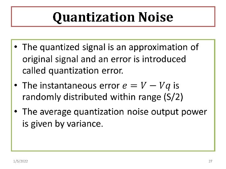
Quantization Noise • 1/5/2022 27
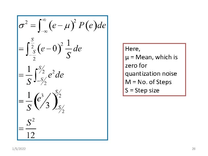
Here, µ = Mean, which is zero for quantization noise M = No. of Steps S = Step size 1/5/2022 28
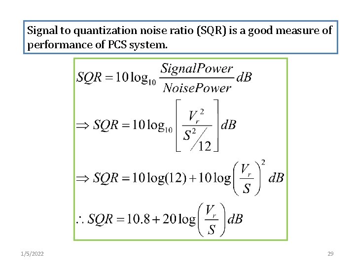
Signal to quantization noise ratio (SQR) is a good measure of performance of PCS system. 1/5/2022 29
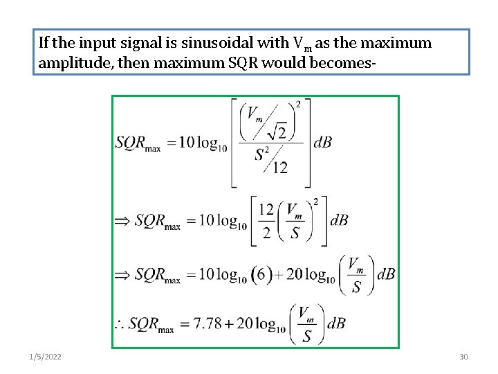
If the input signal is sinusoidal with Vm as the maximum amplitude, then maximum SQR would becomes- 1/5/2022 30
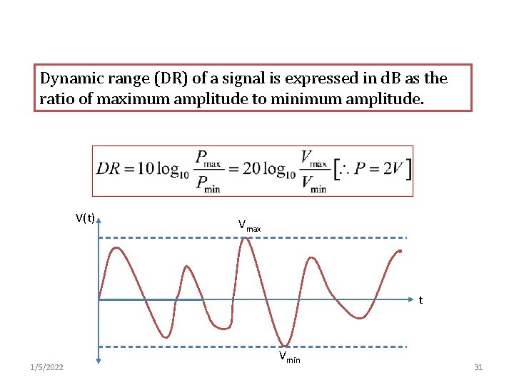
Dynamic range (DR) of a signal is expressed in d. B as the ratio of maximum amplitude to minimum amplitude. V(t) Vmax t 1/5/2022 Vmin 31
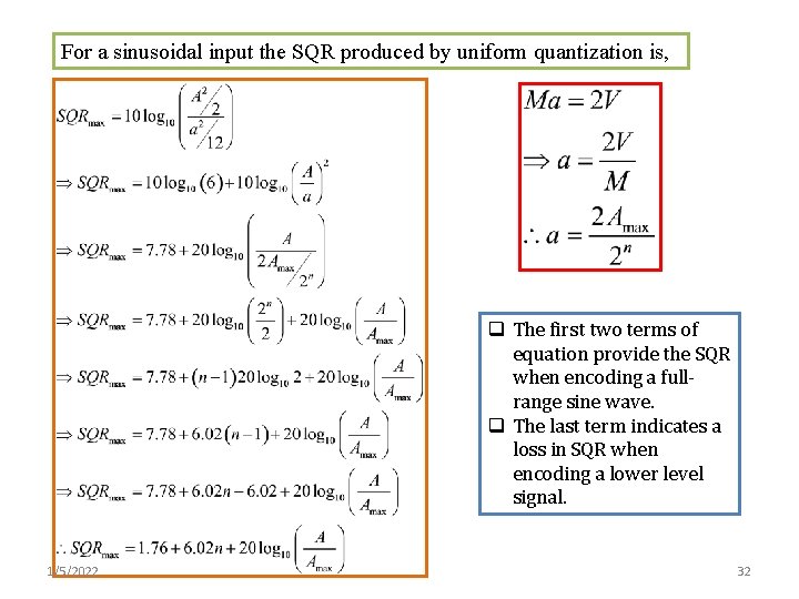
For a sinusoidal input the SQR produced by uniform quantization is, q The first two terms of equation provide the SQR when encoding a fullrange sine wave. q The last term indicates a loss in SQR when encoding a lower level signal. 1/5/2022 32
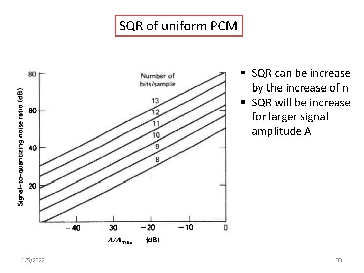
SQR of uniform PCM § SQR can be increase by the increase of n § SQR will be increase for larger signal amplitude A 1/5/2022 33
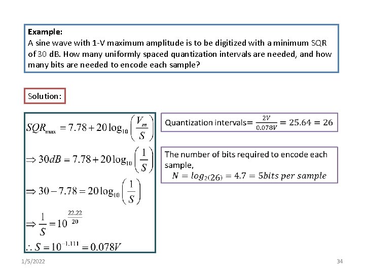
Example: A sine wave with 1 -V maximum amplitude is to be digitized with a minimum SQR of 30 d. B. How many uniformly spaced quantization intervals are needed, and how many bits are needed to encode each sample? Solution: 1/5/2022 34
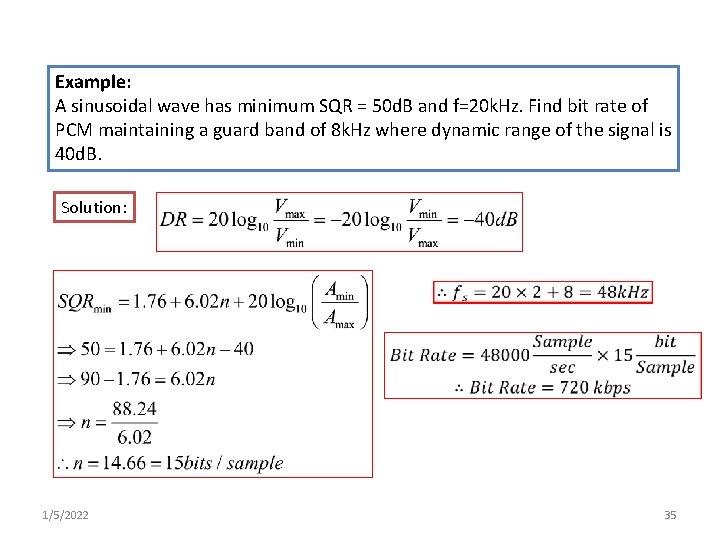
Example: A sinusoidal wave has minimum SQR = 50 d. B and f=20 k. Hz. Find bit rate of PCM maintaining a guard band of 8 k. Hz where dynamic range of the signal is 40 d. B. Solution: 1/5/2022 35
Companding • Due to uniform quantization weak signal suffer more than loud signals (which are least likely to occur( • It is better to vary step size according to input voltage • At first, input is compressed then it is followed by uniform quantization • On receiiver there is an expander to retrive the original signal • Presence of both compression and expansion along with uniform quantization is called companding process. 1/5/2022 36
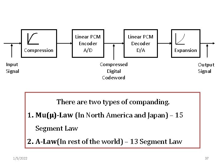
Compression Linear PCM Encoder A/D Linear PCM Decoder D/A Expansion Compressed Digital Codeword Input Signal Output Signal There are two types of companding. 1. Mu(µ)-Law (In North America and Japan) – 15 Segment Law 2. A-Law(In rest of the world) – 13 Segment Law 1/5/2022 37
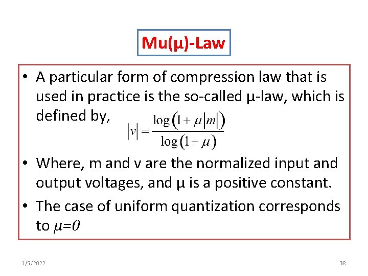
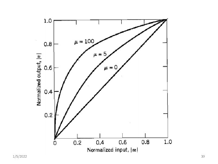
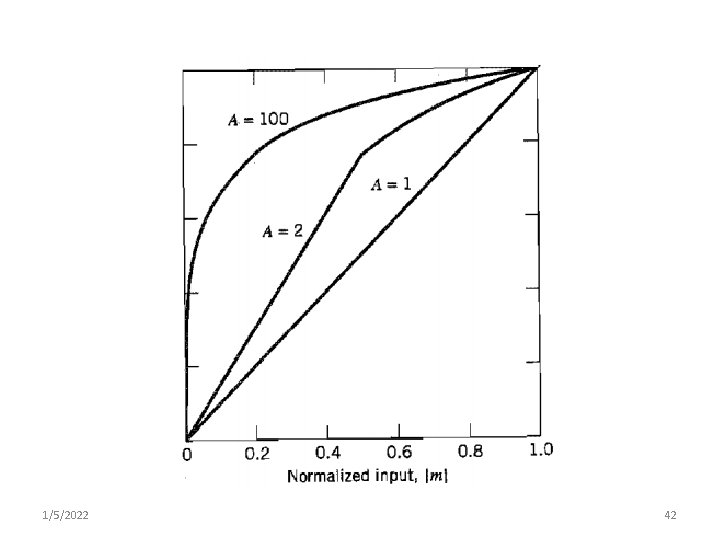
Mu(µ)-Law • A particular form of compression law that is used in practice is the so-called µ-law, which is defined by, • Where, m and v are the normalized input and output voltages, and µ is a positive constant. • The case of uniform quantization corresponds to µ=0 1/5/2022 38
1/5/2022 39
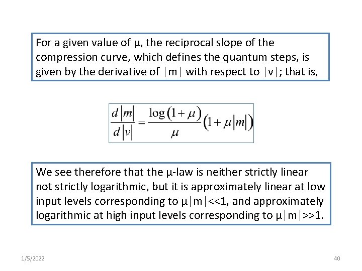
For a given value of µ, the reciprocal slope of the compression curve, which defines the quantum steps, is given by the derivative of |m| with respect to |v|; that is, We see therefore that the µ-law is neither strictly linear not strictly logarithmic, but it is approximately linear at low input levels corresponding to µ|m|<<1, and approximately logarithmic at high input levels corresponding to µ|m|>>1. 1/5/2022 40
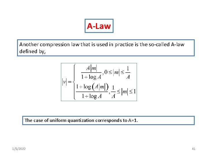
A-Law Another compression law that is used in practice is the so-called A-law defined by, The case of uniform quantization corresponds to A=1. 1/5/2022 41
1/5/2022 42
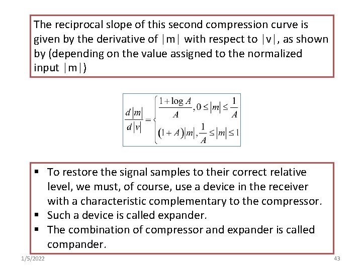
The reciprocal slope of this second compression curve is given by the derivative of |m| with respect to |v|, as shown by (depending on the value assigned to the normalized input |m|) § To restore the signal samples to their correct relative level, we must, of course, use a device in the receiver with a characteristic complementary to the compressor. § Such a device is called expander. § The combination of compressor and expander is called compander. 1/5/2022 43
q For both A-law and mu-law, the dynamic range capability of the compander improves with increasing µ and A, respectively. q The SNR for low-level signals increases at the expense of the SNR for high-level signals. q To accommodate these two conflicting requirements, a compromise is usually made in choosing the value of parameter µ for µ-law and parameter A for the A-law. q The typical values used in practice are: µ=255 and A=87. 6 1/5/2022 44
Differential Coding • Delta or differential coding systems are designed to take advantage of the sample-to-sample redundancies in speech waveforms. • Because of the strong correlation between adjacent speech samples, large abrupt changes in levels do not occur frequently in speech waveforms. • In such situations, it is more efficient to transmit or encode and transmit only the signal changes instead of the absolute value of the samples. • Delta modulation (DM) is a scheme that transmits only the signal changes and differential pulse code modulation (DPCM) encodes the differences and transmits them. 1/5/2022 45
Delta Modulator • A delta modulator may be implemented by simply comparing each new signal sample with previous sample and transmitting the resulting difference signal. • At the receiver end difference signals are added up to construct the absolute signal by using and integrator. • However, such a system being open loop, suffers from the possibility of the receiver output diverging from the transmitter input due to system errors or inaccuracies. • The system can be converted into closed loop system by setting up a feedback path with an integrator at the transmitting end. • The integrator must be identical to the one at the receiving end. 1/5/2022 46
• The difference signal e(b) has only two possible levels. • A positive level indicate that the new sample value is greater than the previous output of the integrator and the negative level the vice versa condition. • A latch provides a delay of one sample time, so that the input is always compared with the previous output. 1/5/2022 47
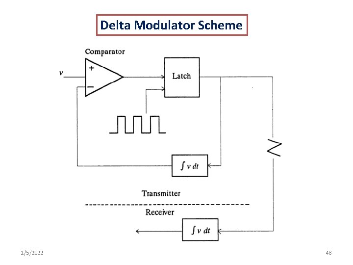
Delta Modulator Scheme 1/5/2022 48
Granular Noise • When the input is constant, the output of the transmitter is an alternating positive and negative pulse train. • This constitutes the quantization noise in delta modulators and also known as granular noise. 1/5/2022 49
Slope Overload Distortion • If the transmitter input signal changes too rapidly, the receiver output is unable to keep up and this phenomenon is known as slope overload. • This problem may be overcome by using a variable slope integrator whose output slope is increased or decreased, depending on the rate of change of the input signal. 1/5/2022 50
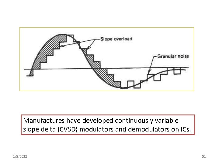
Manufactures have developed continuously variable slope delta (CVSD) modulators and demodulators on ICs. 1/5/2022 51
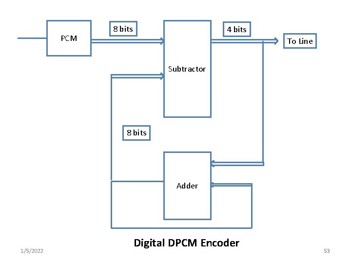
Differential Pulse Code Modulation (DPCM( • In differential pulse code modulation (DPCM), different values are coded berore transmission • Fewer bits are required to encode different values than one required to encode the absolute values • Instead of computing the different values in analog domain & encoding them, they can be computed in digital domain as follows. 1/5/2022 52
PCM 8 bits 4 bits To Line Subtractor 8 bits Adder 1/5/2022 Digital DPCM Encoder 53
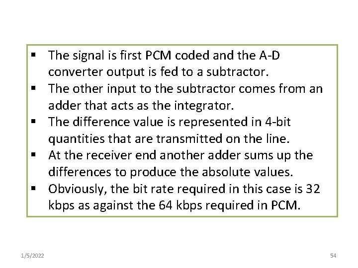
§ The signal is first PCM coded and the A-D converter output is fed to a subtractor. § The other input to the subtractor comes from an adder that acts as the integrator. § The difference value is represented in 4 -bit quantities that are transmitted on the line. § At the receiver end another adder sums up the differences to produce the absolute values. § Obviously, the bit rate required in this case is 32 kbps as against the 64 kbps required in PCM. 1/5/2022 54
Sample Questions: 1. 2. 3. 4. 5. 6. 7. 8. What is voice digitization? What are the advantages of using digital signal? What is foldover distortion? How it can be avoided? What is guard band? What is quantization error? Draw the block diagram of PCM system for speech communication. Why Grey code is preferable in PCM? Define DPCM and Delta modulation. Draw the complete block diagram of delta modulator and show the relation among different parameters of the circuit. 9. Why delta modulation is necessary? 10. What is the impact if large step size in delta modulation? 11. What is the slope overload distortion? How it can be avoided? 12. What do you mean by granular noise? 13. What is the main draw back of uniform quantization? 14. Why companding is necessary? 15. What is dynamic range? 16. All derivations are important. * 1/5/2022 55
- Slides: 55