Commissioning status of MEG II liquid xenon gamma


![resolution (horizontal) [cm] Previous status Position resolution @ 17. 6 Me. V 6 resolution (horizontal) [cm] Previous status Position resolution @ 17. 6 Me. V 6](https://slidetodoc.com/presentation_image_h2/10b34fb3e6f230927cf55a00f9627fb8/image-6.jpg)


- Slides: 25

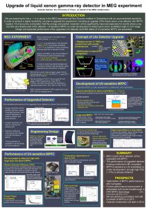
Commissioning status of MEG II liquid xenon gamma detector towards the start of the physics run Kei Ieki for the MEG II collaboration ICEPP, UTokyo 76 th JPS annual meeting

2 Upper limit history • charged Lepton Flavor Violation (c. LFV) can never be observed in SM framework. • On the other hand, many well motivated BSMs predicts c. LFV e. g. SUSYseesaw Dee. Me COMET-I • Experimental sensitivities are already in the region predicted by BSM prediction (SUSY-seesaw etc. ) MEG Mu 3 e-I MEG II Mu 3 e-II COMET-II Mu 2 e

3 Signal and BG MEG sensitivity was limited by accidental BG: Accidental BG Signal ∝ (beam rate)2 e Improvement of detector resolution is important! e

MEG II experiment BG tagging detector 4

5 MEG II upgrade! 2 -inch PMT In MC, factor 2 improvements are expected for the position and energy resolution Needs to be proved
![resolution horizontal cm Previous status Position resolution 17 6 Me V 6 resolution (horizontal) [cm] Previous status Position resolution @ 17. 6 Me. V 6](https://slidetodoc.com/presentation_image_h2/10b34fb3e6f230927cf55a00f9627fb8/image-6.jpg)
resolution (horizontal) [cm] Previous status Position resolution @ 17. 6 Me. V 6

7 Updates in 2020 (小林 14 a. T 2 -2) (恩田 14 a. T 2 -3) Items to be studied: Study in 2020 commissioning run with limited number of readout channels Readout channels in 2020 read not read

8 175 mm 80 mm LH 2 target 200 mm 46 mm

Test of energy scale linearity (conversion depth = 2 -10 cm) 55 Me. V 83 Me. V 129 Me. V 9

10 Test of CH 2 target • LH 2 target is not easy to handle. • Cooling (20 K) by LHe requires time, safety checks • Another candidate is CH 2 • Charge exchange rate is expected to be much smaller (1/100), but operation is much easier EBGO vs. EXEC Test with polyethylene target PMT sum waveform

11 MPPC PDE degradation (2019) blue LED ~0. 06%/hour Degradation is not significant for blue light Surface damage? Blue light Passivation layer Si Accumulation of holes near Si interface may cause reduction of carrier collection efficiency Similar phenomena is known for UV photo diode.

PDE degradation studies • Will it stop decreasing? We continued monitoring in 2020, it did not stop. PDE vs. exposure (2017 -2019) 2017 2018 2019 (恩田 2020年次大会) (島田 12 p. T 2 -8) (吉田 12 p. T 2 -9) • Effect on sensitivity? (小川 2020年次大会) - Resolution only changes by <10% - Target sensitivity can still be achieved in 3 -5 years • Can we recover PDE? Yes, by annealing (next pages) PDE vs. exposure (2020 update) 12

PDE recovery by annealing Response to blue LED light while annealing • Annealing (heating) can be done by applying inverse bias (<70 V, ~20 m. A) to the MPPC under light. • In our case, the MPPC temperature must be below ~70 deg. to keep the CFRP board behind MPPC below 45 deg. • In lab test, basic characteristics of spare MPPC was measured before/after annealing. Below 70 deg, gain and crosstalk + afterpulse did not change. Reduction of dark current was observed. • In 2019, annealing was tested for 7 MPPCs in the LXe detector PDE recovery (~ factor 2) was observed! • In 2020, annealing was done for 12 more MPPCs Response to blue LED was monitored. It was clearly correlated with VUV PDE. Annealing can be monitored by LED. VUV PDE recovery vs. response to blue LED 13

14 How do we anneal all channels? Two methods are being considered: A) Joule heat method • Same as what we did so far already tested. �� • Requires high current HV module and cabling ☹ Test HV module (30 ch, high current) Heating circulator B) Hot water circulation in LN 2 cooling pipes • All MPPCs can be heated at a time�� • No cabling required�� • MPPCs are not directly heated Not sure how much we can heat in reasonable time ☹ Method B is easier, but it needs to be tested. Both methods are being prepared. HV module and heating circulator are available. LN 2 pipes

Summary • 15

16 Backup slides

Energy resolution 17

Resolution vs. PDE 18

Sensitivity in two PDE scenarios 19

VUV irradiation @ room temperature 20

21 Annealing Accumulated charges can be removed by annealing (heating). Generate Joule heat by applying reverse bias on MPPC under light (We need special HV source to apply high current. ) We should not exceed temperature limits: MPPC 100 deg. PCB 120 deg. CFRP 45 deg. Glue 65 deg. Reverse bias, room light Vover~7 V, ~11 m. A PCB MPPC CFRP 2016. 7. 7

How much voltage can we apply? PCB temperature should not exceed 45 deg. How much V, I can we apply? TPCB vs. V*I final version (Vbd~53 V) prototype (Vbd~64 V) back side (PCB) 69 V 67 V 65 V 74 V 63 V front side (MPPC) 71 V 79 V • Temperature and V*I have roughly linear relationship. V should be below ~70 V to keep backside of PCB below 45 deg. TMPPC is around 70 deg. • Adjacent channels are also heated to TMPPC~45 deg. 22

23 Does heating cause any damage? We applied reverse voltage Vover=12 -22 V under room light with three spare MPPCs • 20 -100 deg (several hours) • 70 deg, 63 hours • 62 deg, 60 hours I-V curve (62 deg. sample) Then we tested the performance: • I-V curve measurement (all samples) Current reduced for 62 and 70 deg. , samples, while it increased for 100 deg. • Gain, crosstalk + afterpulsing, dark rate measurement (62 deg. sample) Gain, crosstalk + afterpulsing did not change. Dark rate reduced by 15%. No performance degradation except for 100 deg. sample I-V curve (70 deg. sample) before after 21 hours after 60 hours before after 17 hours after 46 hours after 63 hours

Annealing test for installed MPPCs In 2019, we annealed 7 MPPCs in cryostat before filling LXe. LEDs inside the cryostat were used as light source. PDE 2019/PDE 2018 vs. channel ID annealed MPPCs 24

25 Annealing monitoring In 2020, we monitored annealing performed at different voltages. • Response to blue LED was monitored instead of measuring VUV PDE. • Annealing speed is found to depend on voltage and production lot. Relative charge (blue LED) vs. time 69 V, 21. 8 m. A 0 V, 68 V, 20. 3 m. A 0 m. A 68 V, 20. 8 m. A 69 V, 22. 0 m. A • MPPC at 0 V, heated to ~40 deg. by neighbor channel, was also annealed. It might be safer and efficient to do annealing with warm (<45 deg. ) gas. Lot D 67 V, 19. 8 m. A Lot C 67 V, 20 m. A Lot A (Vbd~53 V)
 Cleanroom cleaning services irvine, ca
 Stressed oil volume theory is applicable when
 Lever arm rule liquid liquid extraction
 Nihr ccf
 Fortis furnace commissioning sheet
 Lidl stores with ev charging
 Value based commissioning
 Aecp program army
 Dr nicola burbidge
 Scientist project
 Integrated commissioning and progress system
 Vacuum systems commissioning
 Steps
Steps Commissioning
 Commissioning management systems
 Croydon clinical commissioning group
 Power system commissioning
 Ecs commissioning
 Aabc commissioning group
 C3sc
C3sc Ecs commissioning
 Commissioning cycle
 Commissioning
 Elementos grupo 18
 Propiedades de xenon
 Xenon cos leaks
