CMS PhaseII Trigger Upgrade Sudeshna Banerjee March 8

CMS Phase-II Trigger Upgrade Sudeshna Banerjee March 8, 2018
 Trigger: Choose the interesting events -> top quark, Higgs")
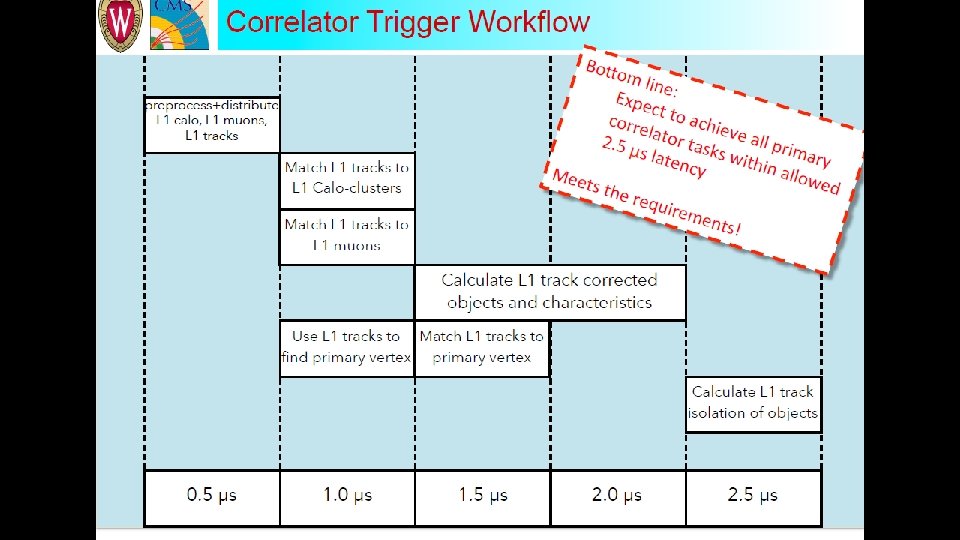
CMS Trigger system (current status) Trigger: Choose the interesting events -> top quark, Higgs boson, exotic particles Triggering is performed in two steps: Level – 1 (Hardware based) High Level Trigger (software algorithms) The beam crossing interval is 25 ns which corresponds to a crossing frequency of 40 MHz. The design output rate limit of the L 1 Trigger is 100 k. Hz, which translates to a calculated maximal output rate of 30 k. Hz, assuming a safety factor of 3. The allowed L 1 Trigger latency, between a given bunch crossing and the distribution of the trigger decision to the detector front-end electronics, is 3. 2 μs. The processing must therefore be pipelined in order to enable a quasi-deadtime-free operation.

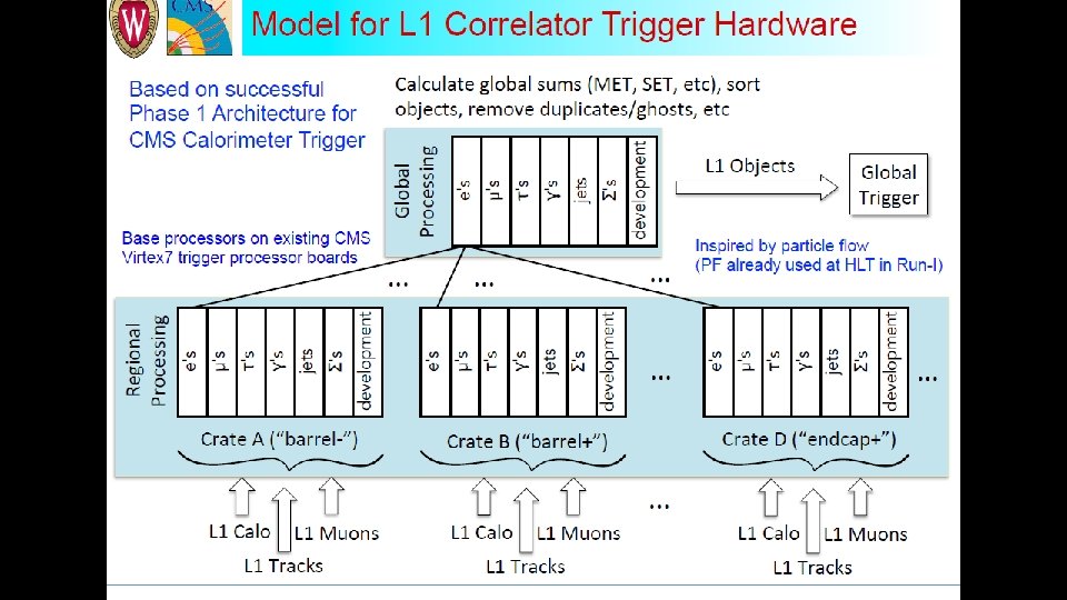
CMS Detector and the first trigger stage – Level 1 TIFR CMS detector Schematic diagram – Phase-II Level-1 trigger

Level-1 Trigger upgrade – Phase II The instantaneous luminosity will increase by a factor of 5 (1034 cm-2 s-1 -> 5*1034 cm-2 s-1). There may not be enough rejection power in the current muon and calorimeter triggers. Upgrade of the Level-1 Trigger system is needed to cope with the higher occupancies and data rates. Several approaches will have to be combined to reach this goal: • More complex operations at an early level, such as residual energy subtraction in the calorimeter trigger; • More sophisticated trigger algorithms such as complex correlations between different types of trigger data, calculation of invariant masses or transverse masses of pairs of trigger objects; • Use of information from additional parts of the CMS detector, in particular from the silicon strip tracker. CMS Detector § § Trigger development targets high end, powerful FPGAs They are becoming more accessible due to the High Level Systhesis (HLS) open CL
 • HLS is an automated design process that")
Introduction to High Level Synthesis (HLS) • HLS is an automated design process that interprets algorithm specification at a high abstraction level and creates digital hardware/RTL code that implements that behavior. • HLS significantly accelerates design time while keeping full control over the choice of optimal architecture exploration, proper level of parallelism and implementation constraints. • Vivado HLS includes a complete design environment with abundant possibilities in the form of pragma directives to finetune hardware generation process from High Level Language (HLL) to Hardware Description Languages (HDL) • HLL input languages: • ANSI-C (GCC 4. 6) • C++ (G++ 4. 6) straightforward integration in CMSSW • Etc… • Vivado HLS C/C++ libraries contain functions and constructs that are optimized for implementation in an FPGA. 5

Electromagnetic Calorimeter Layout ECAL proton η Y Z

Clustering in the Electromagnetic Calorimeter Different Algorithms for Phase 2 Calo. Layer 1 card and synthesized using HLS Vivado • Input used : (17 h*4 f) towers = (17*4*5*5) crystals • Target Device used for latency and performance study • Xilinx Virtex-7 690 T (used in Phase I CTP 7) • Xilinx Virtex Ultra. Scale+ VU 9 P (For Phase 2, just for the illustration purpose, the exact part is still under consideration) 7

Clustering in the Electromagnetic Calorimeter • Step 1: Find peak energy position for each tower (5 x 5 crystals) by using energy weighted sums: CMS Phase-2 Calorimeter Trigger Upgrade 9/17/2020 8

Clustering in the Electromagnetic Calorimeter • Step 2: Calculate the 3 x 3 cluster energy around the peak energy position. • Clusters which have their peaks on tower edges are stitched while considering the entire calo. Layer 1 card. 9

Clustering in the Electromagnetic Calorimeter • Step 3: Clusters belonging to the same card (e. g. 17η x 4φ) and that have their peaks on tower edges are merged. • Merge the energy of smallest cluster to largest cluster • Assign the smallest cluster energy to be 0 Ge. V to avoid double counting later will be merged Cluster in this case will remain 2 x 3, but energy is not lost, because the unclustered energy is reported for each tower • Cluster on card boundaries are stitched in layer-2. 10

Egamma clustering Algorithm for Calo. Layer 1 card • Step 1: Identify for every 5 x 5 crystal ("trigger tower”), the peak crystal position in etaphi • Use energy-weighted position algorithm • Step 2: Calculate the 3 x 3 cluster energy around the peak crystal. • For each tower in a calo-layer 1 card (17 h*4 f) towers , results in : • Peak position in eta and phi • 5 x 5 tower sum • 3 x 3 cluster energy around the seed • Step 3: Merge the 3 x 3 clusters with peak energy at the tower boundaries • For the time being, we have only taken ECAL tower information in the algorithm (no HCAL input) 11
 Target")
HLS Vivado Performance Target Clock used is : 240 MHz (4. 16 ns) Target Device : Xilinx Virtex-7 690 T Latency of 53 clock cycles and 22% (FF) and 35% (LUT) usage of resources Absolute latency : 53*(4. 16/25) = 8. 8 BX ================================ == Performance Estimates ================================ + Timing (ns): * Summary: +----+----------+------+ | Clock | Target| Estimated| Uncertainty| +----+----------+------+ |ap_clk | 4. 16| 3. 64| 0. 52| +----+----------+------+ + Latency (clock cycles): * Summary: +-----+-----+-----+ | Latency | Interval | Pipeline | | min | max | Type | +-----+-----+-----+ | 53| 6| function | +-----+-----+-----+ ================================ == Utilization Estimates ================================ * Summary: +---------+-----+--------+----+ | Name | BRAM_18 K| DSP 48 E| FF | LUT | +---------+-----+--------+----+ |DSP | -| -| -| |Expression | -| -| 0| 21934| |FIFO | -| -| -| |Instance | -| -| 142188| 97904| |Memory | -| -| -| |Multiplexer | -| -| 26229| |Register | -| -| 53300| 9840| +---------+-----+--------+----+ |Total | 0| 0| 195488| 155907| +---------+-----+--------+----+ |Available | 2940| 3600| 866400| 433200| +---------+-----+--------+----+ |Utilization (%) | 0| 0| 22| 35| +---------+-----+--------+----+ 12
 Target")
HLS Vivado Performance Target Clock used is : 320 MHz (3. 12 ns) Target Device : Xilinx Virtex Ultra. Scale+ VU 9 P Latency of 72 clock cycles and 8% (FF) and 13% (LUT) usage of resources Absolute latency : 72*(43. 12/25) = 8. 9 BX ================================ == Performance Estimates ================================ + Timing (ns): * Summary: +----+----------+------+ | Clock | Target| Estimated| Uncertainty| +----+----------+------+ |ap_clk | 3. 12| 3. 02| 0. 39| +----+----------+------+ + Latency (clock cycles): * Summary: +-----+-----+-----+ | Latency | Interval | Pipeline | | min | max | Type | +-----+-----+-----+ | 72| 8| function | +-----+-----+-----+ ================================ == Utilization Estimates ================================ * Summary: +---------+-----+--------+----+ | Name | BRAM_18 K| DSP 48 E| FF | LUT | +---------+-----+--------+----+ |DSP | -| -| -| |Expression | -| -| 0| 29153| |FIFO | -| -| -| |Instance | -| -| 134985| 96976| |Memory | -| -| -| |Multiplexer | -| -| 28647| |Register | -| -| 56513| 10095| +---------+-----+--------+----+ |Total | 0| 0| 191498| 164871| +---------+-----+--------+----+ |Available | 4320| 6840| 2364480| 1182240| +---------+-----+--------+----+ |Utilization (%) | 0| 0| 8| 13| +---------+-----+--------+----+ 13

More Examples: • • • Estimate the missing energy in the event Identify tau leptons Link energy cluster with tracks for better particle id All these methods will be used in order to design a better trigger at Level 1 to discard uninteresting events

Current status • At TIFR we have setup simple algorithms for pattern recognition on our existing FPGAs (Kintex). • These algorithms were tried on the Wisconsin system using advanced FPGAs (xilinx virtex-7 690 T). • We bought in 2017 a Kintex 7 FPGA kit with ZYNQ processor, learnt how to work with it, then tested the algorithms on it. • Our studies in collaboration with the Wisconsin group on the use of HLS firmware for implementing trigger algorithms on FPGAs have been included in the interim document on Phase-II trigger upgrade which has been released. • The Upgrade Trigger TDR is the next step which is due in 2020. • New FPGA (Ultrascale+, ZYNQ) has been received recently. We will now do a comparative study of performance of different FPGA systems. Offline algorithms: We have been studying efficiency, response and resolution of AK 8 jets with the aim of building an algorithm to trigger on events with boosted top quarks using jet substructure. This study is being compared with the AK 4 jet performance. A poster is on display on this topic.

BACKUP

• Currently, one or two system architectures for the generic trigger processor boards are being designed and evaluated by the collaboration. • Possible arrangement of boards and links together with processing functions to be performed by each board are also being worked at. • These functionalities will be realised by expansion mezzanines and supplemental FPGA processor boards. • We will procure high FPGA/So. C development/evaluation kits and will initially build the functionalities mentioned above. • Apart from helping us upgrade our technology skills, this process/method also allows us decouple risk of building high cost hardware straight away. • The kits will help both firmware and algorithm development work. Xilinx EK-Z 7 -ZC 706 -G development kit
- Slides: 20