
Chapter 2 Fundamentals of Data and Signals Introduction
- Slides: 31
Chapter 2 Fundamentals of Data and Signals
Introduction v Data are entities that convey meaning v Signals are the electric or electromagnetic encoding of data v Computer networks and data/voice communication systems transmit signals v Data and signals can be analog or digital 2
Why are we interested? v Layer 1 of the OSI model is all about the physical transmission of signals over media v Point-to-point transmission of data across nodes: Ø Ø Ø Specifies the type of connection and the signals that pass through it Signals can be analog or digital, broadband or baseband The capacity (throughput) of the network depends on the type of cabling used 3
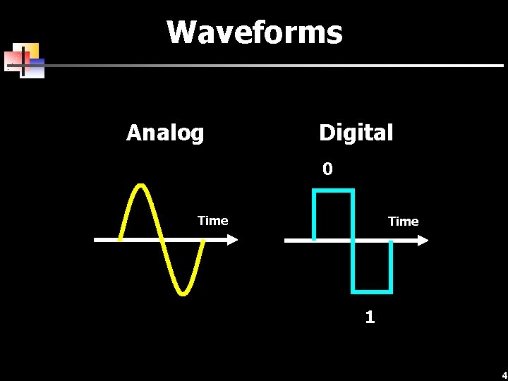
Waveforms Analog Digital 0 Time 1 4
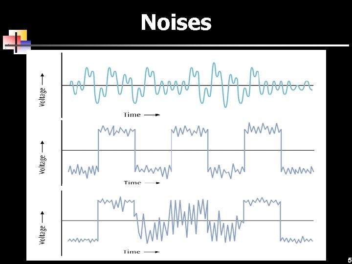
Noises 5
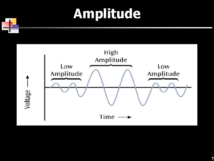
Single properties v Amplitude: Ø The “height” of the wave above (or below) a central point, often measured in volts (V) v Frequency: Ø The number of waves that pass a given point per second, measured in Hertz (Hz) v Wavelength: Ø The distance from the start to the end of the wave, measured in meters (m) v Phase: Ø Position of the waveform at a given time, measured in degrees of shift (o) 6
Amplitude 7
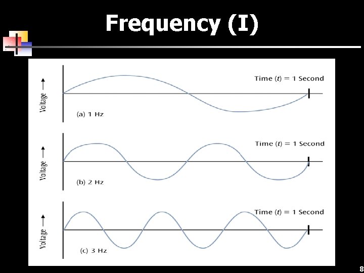
Frequency (I) 8
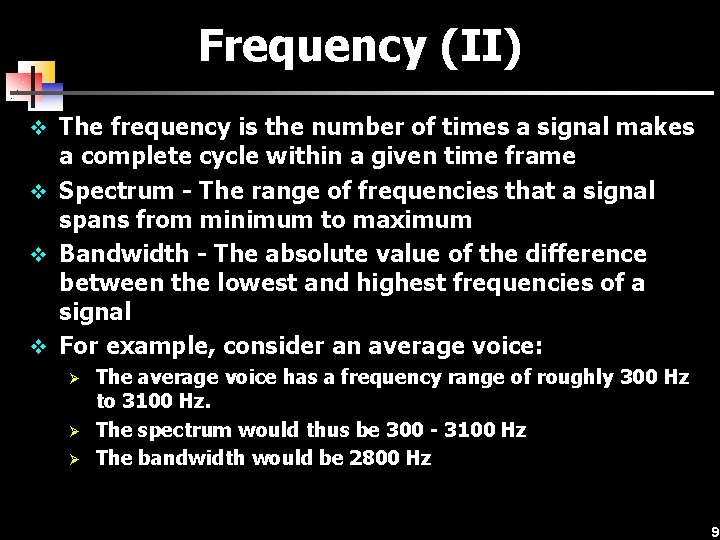
Frequency (II) v The frequency is the number of times a signal makes a complete cycle within a given time frame v Spectrum - The range of frequencies that a signal spans from minimum to maximum v Bandwidth - The absolute value of the difference between the lowest and highest frequencies of a signal v For example, consider an average voice: Ø Ø Ø The average voice has a frequency range of roughly 300 Hz to 3100 Hz. The spectrum would thus be 300 - 3100 Hz The bandwidth would be 2800 Hz 9
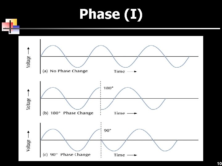
Phase (I) 10
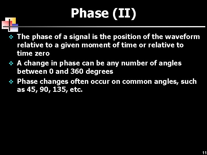
Phase (II) v The phase of a signal is the position of the waveform relative to a given moment of time or relative to time zero v A change in phase can be any number of angles between 0 and 360 degrees v Phase changes often occur on common angles, such as 45, 90, 135, etc. 11
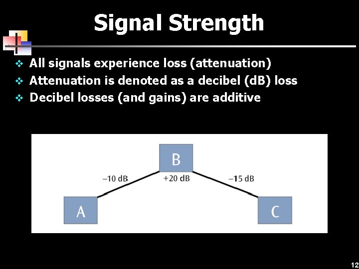
Signal Strength v All signals experience loss (attenuation) v Attenuation is denoted as a decibel (d. B) loss v Decibel losses (and gains) are additive 12
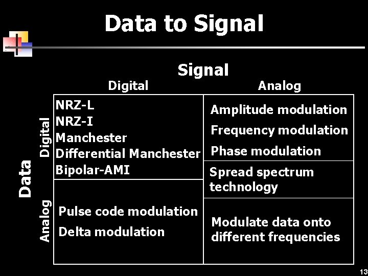
Data to Signal Analog Data Digital Signal NRZ-L NRZ-I Manchester Differential Manchester Bipolar-AMI Pulse code modulation Delta modulation Analog Amplitude modulation Frequency modulation Phase modulation Spread spectrum technology Modulate data onto different frequencies 13
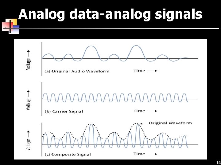
Analog data-analog signals 14
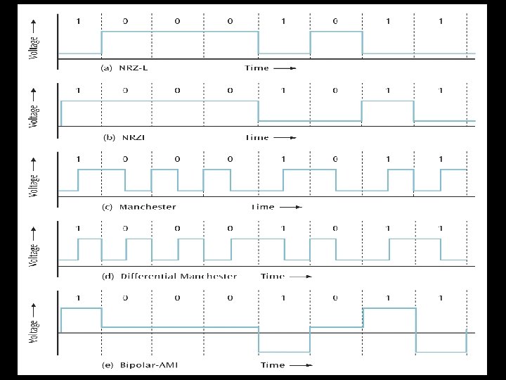
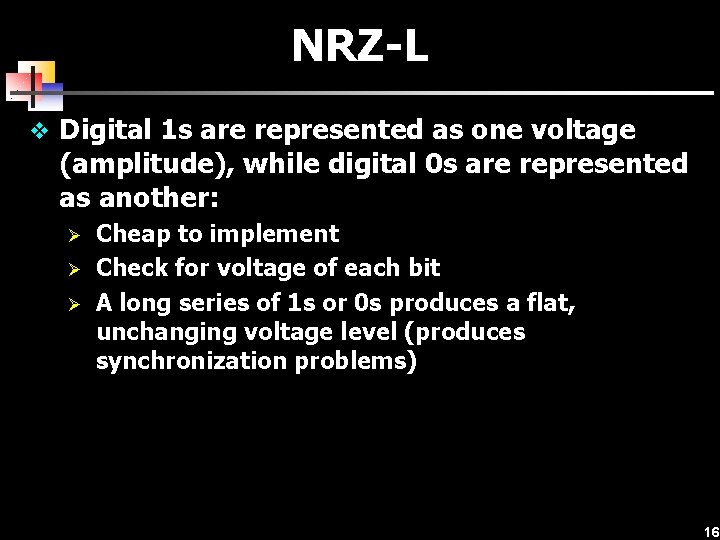
NRZ-L v Digital 1 s are represented as one voltage (amplitude), while digital 0 s are represented as another: Ø Ø Ø Cheap to implement Check for voltage of each bit A long series of 1 s or 0 s produces a flat, unchanging voltage level (produces synchronization problems) 16
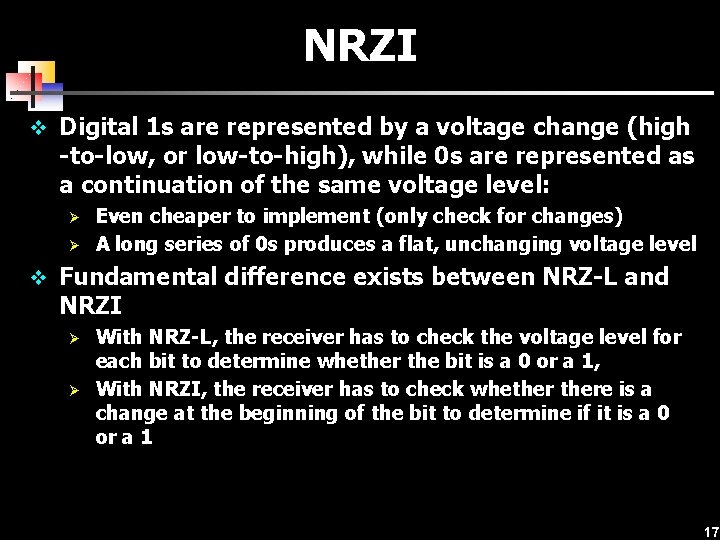
NRZI v Digital 1 s are represented by a voltage change (high -to-low, or low-to-high), while 0 s are represented as a continuation of the same voltage level: Ø Ø Even cheaper to implement (only check for changes) A long series of 0 s produces a flat, unchanging voltage level v Fundamental difference exists between NRZ-L and NRZI Ø Ø With NRZ-L, the receiver has to check the voltage level for each bit to determine whether the bit is a 0 or a 1, With NRZI, the receiver has to check whethere is a change at the beginning of the bit to determine if it is a 0 or a 1 17
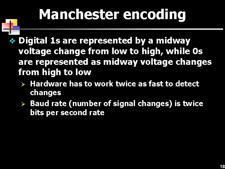
Manchester encoding v Digital 1 s are represented by a midway voltage change from low to high, while 0 s are represented as midway voltage changes from high to low Ø Ø Hardware has to work twice as fast to detect changes Baud rate (number of signal changes) is twice bits per second rate 18
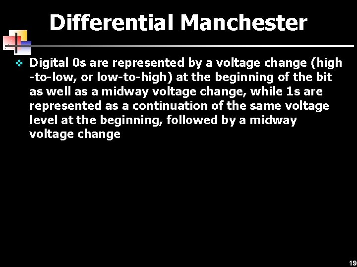
Differential Manchester v Digital 0 s are represented by a voltage change (high -to-low, or low-to-high) at the beginning of the bit as well as a midway voltage change, while 1 s are represented as a continuation of the same voltage level at the beginning, followed by a midway voltage change 19
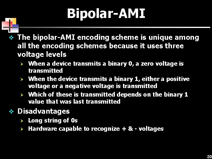
Bipolar-AMI v The bipolar-AMI encoding scheme is unique among all the encoding schemes because it uses three voltage levels Ø Ø Ø When a device transmits a binary 0, a zero voltage is transmitted When the device transmits a binary 1, either a positive voltage or a negative voltage is transmitted Which of these is transmitted depends on the binary 1 value that was last transmitted v Disadvantages Ø Long string of 0 s Ø Hardware capable to recognize + & - voltages 20
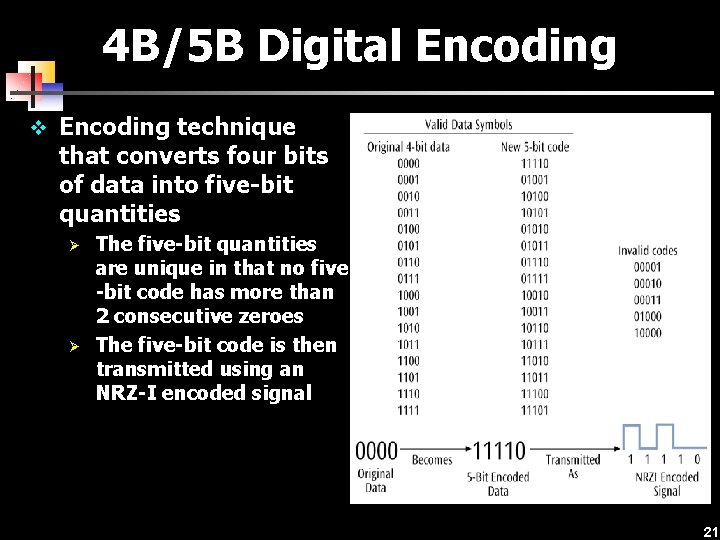
4 B/5 B Digital Encoding v Encoding technique that converts four bits of data into five-bit quantities Ø Ø The five-bit quantities are unique in that no five -bit code has more than 2 consecutive zeroes The five-bit code is then transmitted using an NRZ-I encoded signal 21
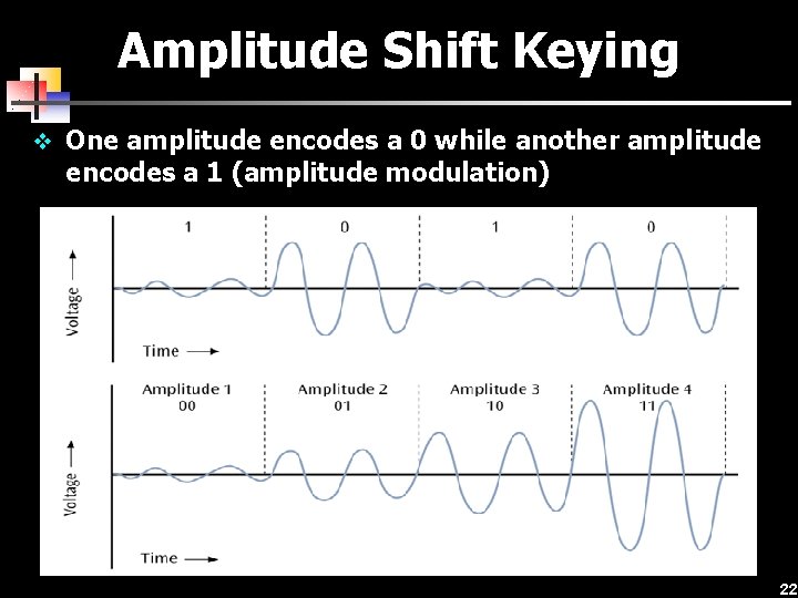
Amplitude Shift Keying v One amplitude encodes a 0 while another amplitude encodes a 1 (amplitude modulation) 22
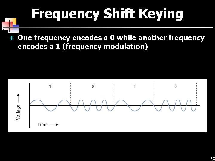
Frequency Shift Keying v One frequency encodes a 0 while another frequency encodes a 1 (frequency modulation) 23
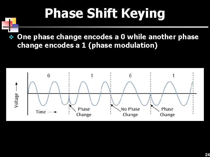
Phase Shift Keying v One phase change encodes a 0 while another phase change encodes a 1 (phase modulation) 24
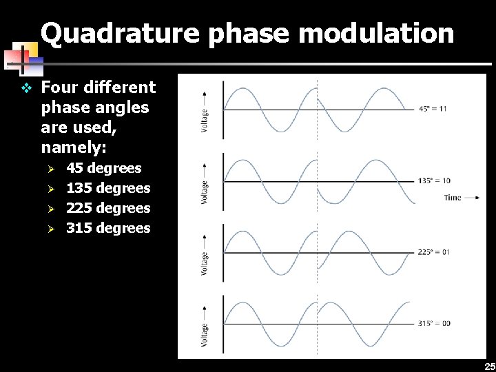
Quadrature phase modulation v Four different phase angles are used, namely: Ø Ø 45 degrees 135 degrees 225 degrees 315 degrees 25
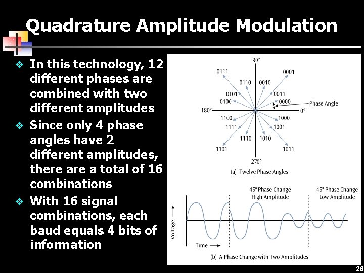
Quadrature Amplitude Modulation v In this technology, 12 different phases are combined with two different amplitudes v Since only 4 phase angles have 2 different amplitudes, there a total of 16 combinations v With 16 signal combinations, each baud equals 4 bits of information 26
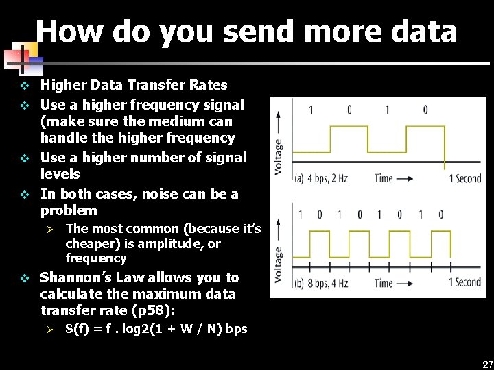
How do you send more data v Higher Data Transfer Rates v Use a higher frequency signal (make sure the medium can handle the higher frequency v Use a higher number of signal levels v In both cases, noise can be a problem Ø The most common (because it’s cheaper) is amplitude, or frequency v Shannon’s Law allows you to calculate the maximum data transfer rate (p 58): Ø S(f) = f. log 2(1 + W / N) bps 27
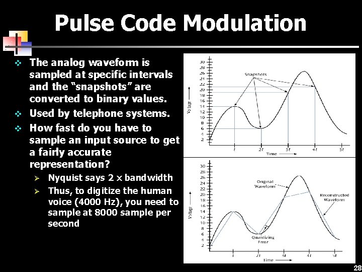
Pulse Code Modulation v The analog waveform is sampled at specific intervals and the “snapshots” are converted to binary values. v Used by telephone systems. v How fast do you have to sample an input source to get a fairly accurate representation? Ø Ø Nyquist says 2 x bandwidth Thus, to digitize the human voice (4000 Hz), you need to sample at 8000 sample per second 28
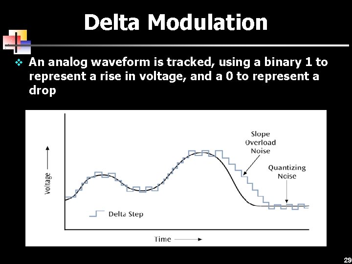
Delta Modulation v An analog waveform is tracked, using a binary 1 to represent a rise in voltage, and a 0 to represent a drop 29
Spread Spectrum Technology v A secure encoding technique that uses multiple frequencies or codes to transmit data v Two basic spread spectrum technologies: Ø Ø Frequency hopping spread spectrum Direct sequence spread spectrum 30
Data Codes v The set of all textual characters or symbols and their corresponding binary patterns is called a data code. v There are two basic data code sets plus a third code set that has interesting characteristics: Ø Ø Ø EBCDIC ASCII Unicode ü ü ü Each character is 16 bits A large number of languages / character sets For example: n n n T equals 0000 0101 0100 r equals 0000 0111 0010 a equals 0000 0110 0001 31