CEPC injection and extraction Septa and kickers RD


 ②Booster LE injection system")


- Slides: 19
CEPC injection and extraction Septa and kickers R&D progress Jinhui Chen Injection group 2019 -05 -31 Circular Electron-Positron Collider
Overview of CEPC injection and extraction systems 2
Layout of the accelerators 120 Ge. V e+ e- 100 km 10 -120 Ge. V 1. 2 km 3
CEPC injection and extraction systems ①DR injection and Extraction system(e+) ②Booster LE injection system (e+, e-) ③Booster Extraction system 1 (e+, e-) ④Collider off-axis injection system (e+, e-) ⑤Booster Extraction system 2 (e+, e-) ⑥Booster HE injection system (e+, e-) ⑦Collider swap out injection system (e+, e-) ⑧Collider swap out extraction system (e+, e-) ⑨Collider beam dump system 4
Parameters of the Linac and DR 75. 4 m Bunch spacing of the Linac=10 ms How long are the straight sections for inj. &ext. ? Damping ring energy=1. 1 Ge. V Circumference=75. 4 m,Revolution period=251. 4 ns Filling mode: 2 bunches, uniform Bunch spacing=125 ns Bunch spacing of the Linac and the DR are different. So, bunch by bunch injection and extraction is necessary for the DR. • Lambertson: length=0. 5 m, deflection angle=100 mrad, B=0. 72 T thickness of septum sheet? Leakage field=? • Fast kicker: pulse width<250 ns, repetition rate=100 Hz, length=0. 25 m, deflection angle=1. 5 mrad, B=0. 02 T • 125 ns • • 5
Parameters of the booster-Low energy • 3 operation mode:Higgs,W,Z • Circumference=100 km,Revolution period=333. 6 us • Filling mode:uniform? 242 bunches 680 ns Higgs 1524 bunches 210 ns 6000 bunches 25 ns? W Z • Bunch spacing of the Linac and the booster are different. So, it has to be bunch by bunch injection for the booster at low energy. • The damping time of the booster at low energy is 90. 7 s. So, it is impossible to approach beam accumulate in low energy booster. On-axis injection based on fast kicker is reasonable scheme for low energy beam injection from the Linac. • fast kicker : pulse width<50 ns? , repetition rate=100 Hz • Magnet aperture=40 mm(round diameter? Quadrupole? ) • Kicker aperture(H×V)=? good field region(H×V)=? Length=0. 3 m, deflection=0. 25 mrad, B=0. 028 T • Lambertson: length=1 m, deflection=22 mrad, B=0. 72 T leakage field? 6
Parameters of the booster-High energy reinjection? 7
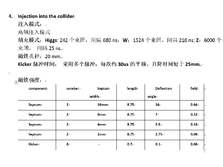
Parameters of the collider Where is the beam dump system? • • • 3 operation mode:Higgs,W,Z Circumference=100 km,Revolution period=333. 6 us Filling mode:uniform? 242 bunches 680 ns? Higgs 1524 bunches 210 ns 12000 bunches 25 ns W Z 8
Booster Extraction 242 bunches 680 ns? booster 210 ns Higgs 242 bunches collider l l l 1524 bunches 680 ns? 25 ns? W 1524 bunches 210 ns Higgs 6000 bunches Z 12000 bunches Uniform? ? 25 ns W Z Bunch by bunch extraction or bunch train fast extraction? It would take long time for bunch by bunch extraction because long damping time of around 50 ms in the collider. Bunch train extraction required the both rings have the same filling pattern. 300 us 200 ns Single turn extraction? ? Be difficult for kicker pulser. 200 ns 平顶宽度=300 us,如果采用脉冲形成线PFL储能的话需要30 km长,阻抗 5欧姆,10根 50欧姆的电缆并联,总计电缆长度为 300 km。 9
MR Off-axis injection for the W and Z mode l l l Bunch by bunch extraction or bunch train injection? It would take long time for bunch by bunch extraction because long damping time of around 50 ms in the collider. Bunch train extraction required the both rings have the same filling pattern. stored bunch train Septum sheet Injected bunch train 300 us 200 ns Single turn injection? ? Be difficult for kicker pulser. 200 ns 10
MR On-axis swap out injection for the Higgs mode 242 bunches 680 ns? The beam is kicked bunch by bunch? ? Repetition rate=? ? Higgs 11
Beam dump system l Fast kicker Location: between IP 3 and IP 4? l Fast kicker: Tr=35 ns? (bunch spacing=27. 5 ns in Z mode) l Fast kicker: Tf=330 us? l Kick angle? . . 330 us 12
Important parameters input l Injection & extraction schemes l Filling pattern l l l l Injection & extraction section layout, including injection and extraction direction Beam stay clearance of Kickers and septums Strength of kickers and septums,some input parameters are not reasonalble Thickness of septum Parameters of kicker pulse: waveform ? rise/fall time(? %-? %), flat-top( duration, flatness), repetition rate. Magnet type? Beam impedance budget. Another potential new technology? Non-linear kicker, puled sextupole (trapezoid waveform? ) 13
Hardware designs for CEPC injection and extraction systems Contributed by Kang Wen 14
Preliminary design of kicker magnets ü To get an high excitation efficiency, all the kicker magnets will have a window type cores made by two C-type ferrite blocks. ü All the kicker magnets will be put inside the vacuum tanks so that the fast pulsed field can directly kick the beam without time delay and amplitude attenuation. ü To avoid the coupling between particle beam and the ferrite blocks, two thin copper plates will be inserted between the touched surfaces of two C-type blocks. 15
Preliminary design of septum magnets ü There are two types of septum magnets often used for beam injection and extraction of accelerators. One is C-type septum magnet, another is Lambertson type septum magnet. ü Due to high reliability and stability, Lambertson magnets are selected as the septum magnet for the beam injection and extraction of all the CEPC accelerators. ü By using several shielding measures, the leakage field along the orbit of the circulating beam can be reduced down to 5 E-4 of the main field in the magnet gap. 16
Preliminary design of septum magnets The main parameters of the Lambertson magnets DR-INJ-EXT- BST-EXTMR-EXTLAM LAM LAM-01 LAM-02 Number 2 2 16 20 20 Eff. length(m) 2 2 1. 875 1. 75 Max. field(T) 0. 18 0. 366 0. 58 0. 64 0. 32 Septa thick(mm) 10 10 4 Gap(mm) 64 44 44 24 24 GFR(mm) 60 40 40 20 20 Leakage field < 0. 001 0. 1% Amp. turns(AT) 9442 13200 20917 12590 6295 Current (A) 472 440 581 420 393 Jc(A/mm 2) 3. 27 3. 04 4. 02 2. 9 2. 72 Resistance(Ω) 0. 011 0. 016 0. 019 0. 014 0. 007 Voltage(V) 5. 26 7. 16 10. 8 5. 9 2. 9 Power loss(k. W) 2. 48 3. 15 6. 30 2. 47 1. 15 ΔP(kg/cm 2) 6 6 6 Water flow(l/s) 0. 52 0. 79 0. 73 0. 86 0. 66 ΔT(℃) 1. 13 1 2 1 1 L/W/H(m) 2. 2/0. 7/0. 4 2. 2/0. 5/0. 4 2. 1/0. 5/0. 4 2. 0/0. 4/0. 3 1. 9/0. 3 Weight(t) 2. 9 2. 5 1. 7 1. 0 17
END 18