CEASACLAY HIGH VOLTAGE MODULATOR FOR PULSED KLYSTRONS CEA

- Slides: 33
CEA-SACLAY HIGH VOLTAGE MODULATOR FOR PULSED KLYSTRONS üCEA Saclay RF teststand üMODULATOR first design ü HV and RF tests with the first design ü MODULATOR new design ü HV and RF tests with the new design ü Conclusions 1 A. Hamdi CEA/IRFU/SACM 5 th CWRF workshop, march 2008, Geneva
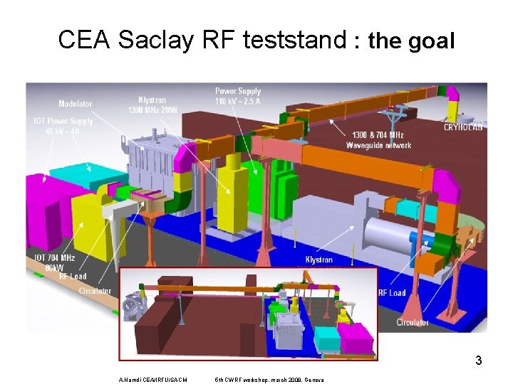
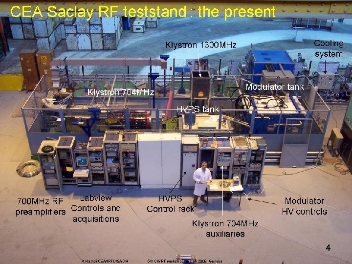
CEA Saclay RF teststand • Movement of the whole SEA (Service d’Etude des Accélérateurs) infrastructures from l’Orme des merisiers to Saclay center 2005 -2006 • New power supply (300 KVA) , new cooling etc… and their comissioning 2 A. Hamdi CEA/IRFU/SACM 5 th CWRF workshop, march 2008, Geneva
CEA Saclay RF teststand : the goal 3 A. Hamdi CEA/IRFU/SACM 5 th CWRF workshop, march 2008, Geneva
4 A. Hamdi CEA/IRFU/SACM 5 th CWRF workshop, march 2008, Geneva
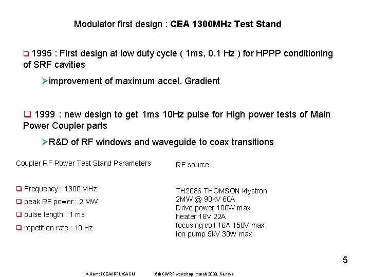
Modulator first design : CEA 1300 MHz Test Stand q 1995 : First design at low duty cycle ( 1 ms, 0. 1 Hz ) for HPPP conditioning of SRF cavities Øimprovement of maximum accel. Gradient q 1999 : new design to get 1 ms 10 Hz pulse for High power tests of Main Power Coupler parts ØR&D of RF windows and waveguide to coax transitions Coupler RF Power Test Stand Parameters RF source : q Frequency : 1300 MHz TH 2086 THOMSON klystron 2 MW @ 90 k. V 60 A Drive power 100 W max heater 18 V 22 A focusing coil 16 A 150 V max ion pump 5 k. V 30 W max q peak RF power : 2 MW q pulse length : 1 ms q repetition rate : 10 Hz 5 A. Hamdi CEA/IRFU/SACM 5 th CWRF workshop, march 2008, Geneva
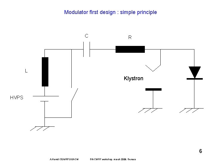
Modulator first design : simple principle C R L Klystron HVPS 6 A. Hamdi CEA/IRFU/SACM 5 th CWRF workshop, march 2008, Geneva
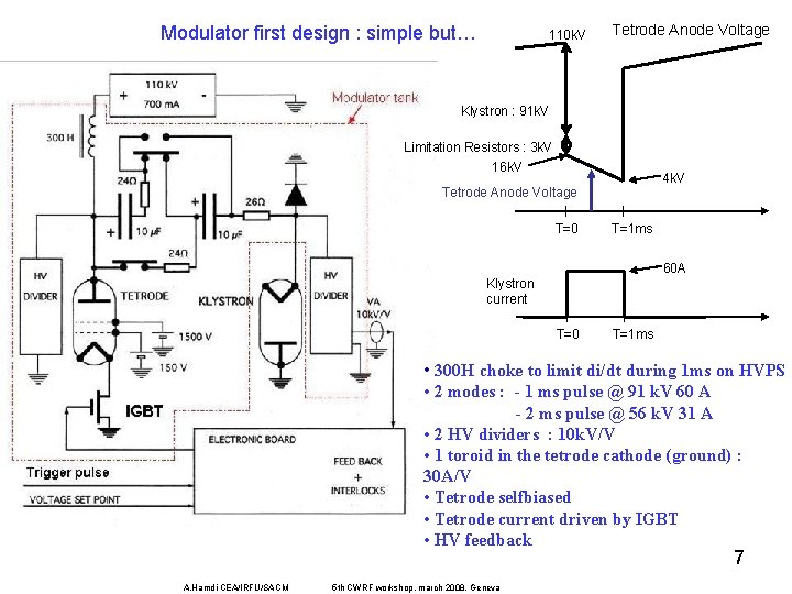
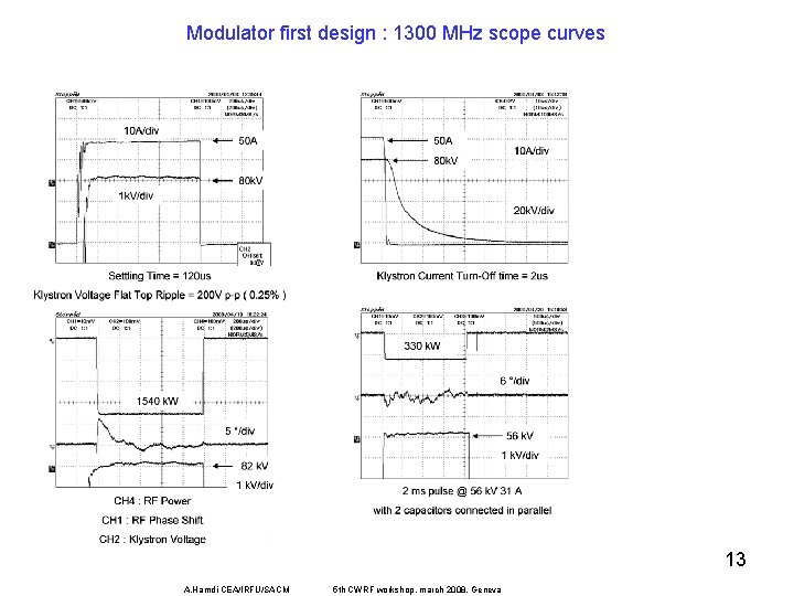
Modulator first design : simple but… 110 k. V Tetrode Anode Voltage Klystron : 91 k. V Limitation Resistors : 3 k. V 16 k. V 4 k. V Tetrode Anode Voltage T=0 T=1 ms 60 A Klystron current T=0 T=1 ms • 300 H choke to limit di/dt during 1 ms on HVPS • 2 modes : - 1 ms pulse @ 91 k. V 60 A - 2 ms pulse @ 56 k. V 31 A • 2 HV dividers : 10 k. V/V • 1 toroid in the tetrode cathode (ground) : 30 A/V • Tetrode selfbiased • Tetrode current driven by IGBT • HV feedback 7 A. Hamdi CEA/IRFU/SACM 5 th CWRF workshop, march 2008, Geneva
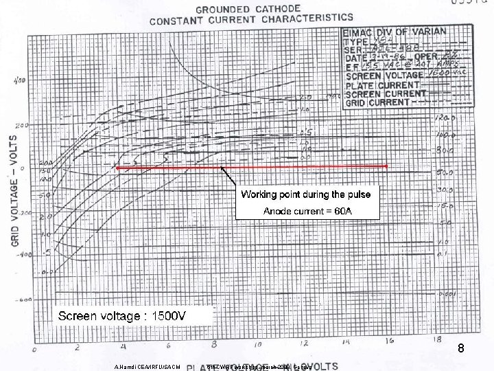
8 A. Hamdi CEA/IRFU/SACM 5 th CWRF workshop, march 2008, Geneva
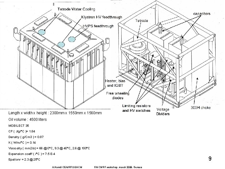
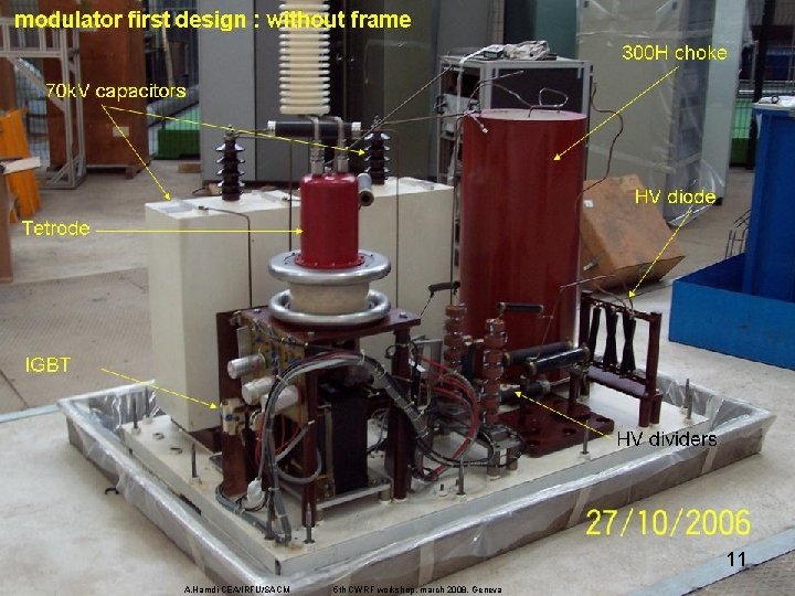
Length x width x height : 2300 mm x 1550 mm x 1560 mm Oil volume : 4500 liters MOBILECT 35 CP ( J/g/°C )= 1. 84 Density ( g/Cm 3 ) = 0. 87 K ( W/m/°C ) = 0. 14 Viscosity ( mm 2/s) = 66 @ 0°C, 9. 3 @ 40°C, 2. 6 @ 100°C Expension coeff ( /°C ) = 7. 5 E-4 9 Epsilonr = 2. 3 @ 25°C A. Hamdi CEA/IRFU/SACM 5 th CWRF workshop, march 2008, Geneva
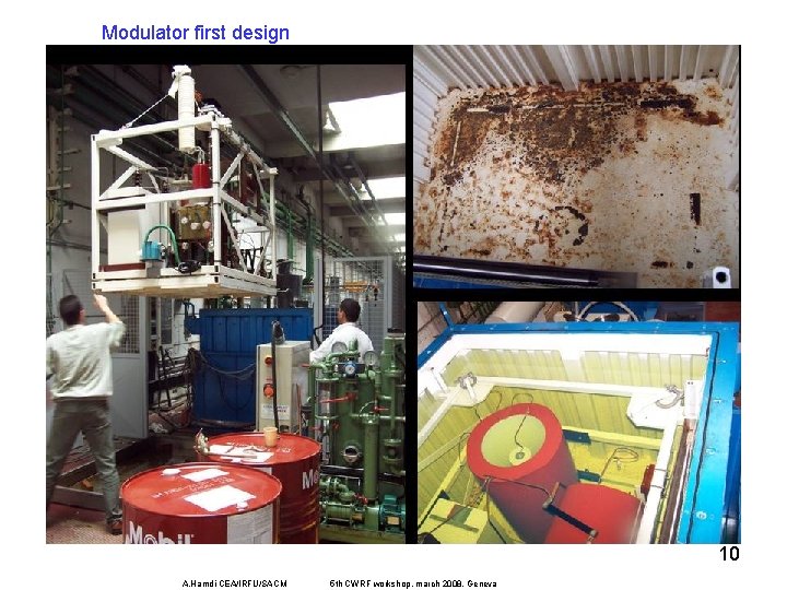
Modulator first design 10 A. Hamdi CEA/IRFU/SACM 5 th CWRF workshop, march 2008, Geneva
11 A. Hamdi CEA/IRFU/SACM 5 th CWRF workshop, march 2008, Geneva
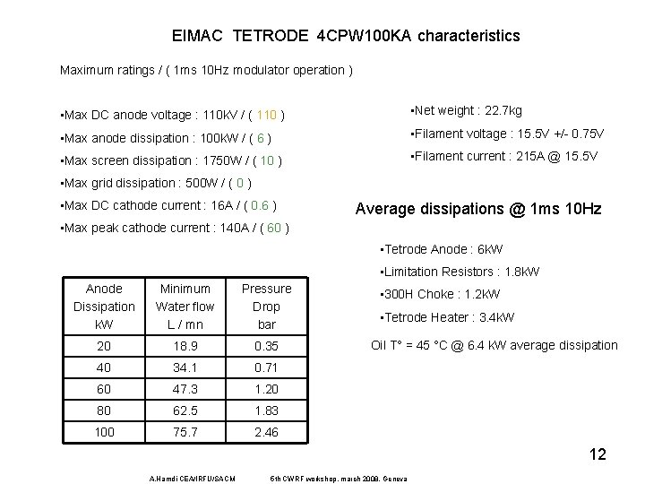
EIMAC TETRODE 4 CPW 100 KA characteristics Maximum ratings / ( 1 ms 10 Hz modulator operation ) • Max DC anode voltage : 110 k. V / ( 110 ) • Net weight : 22. 7 kg • Max anode dissipation : 100 k. W / ( 6 ) • Filament voltage : 15. 5 V +/- 0. 75 V • Max screen dissipation : 1750 W / ( 10 ) • Filament current : 215 A @ 15. 5 V • Max grid dissipation : 500 W / ( 0 ) • Max DC cathode current : 16 A / ( 0. 6 ) Average dissipations @ 1 ms 10 Hz • Max peak cathode current : 140 A / ( 60 ) • Tetrode Anode : 6 k. W • Limitation Resistors : 1. 8 k. W Anode Dissipation k. W Minimum Water flow L / mn Pressure Drop bar 20 18. 9 0. 35 40 34. 1 0. 71 60 47. 3 1. 20 80 62. 5 1. 83 100 75. 7 2. 46 • 300 H Choke : 1. 2 k. W • Tetrode Heater : 3. 4 k. W Oil T° = 45 °C @ 6. 4 k. W average dissipation 12 A. Hamdi CEA/IRFU/SACM 5 th CWRF workshop, march 2008, Geneva
Modulator first design : 1300 MHz scope curves 13 A. Hamdi CEA/IRFU/SACM 5 th CWRF workshop, march 2008, Geneva
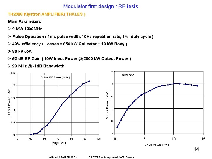
Modulator first design : RF tests TH 2086 Klystron AMPLIFIER( THALES ) Main Parameters Ø 2 MW 1300 MHz Ø Pulse Operation ( 1 ms pulse width, 10 Hz repetition rate, 1% duty cycle ) Ø 40% efficiency ( Losses = 650 k. W Collector + 13 k. W Body ) Ø 86 k. V 55 A Ø 53 d. B RF Gain ( 10 W Input Power @ 2000 k. W Output Power ) Ø 20 MHz @ -1 d. B Bandwidth 2. 5 86 k. V 55 A Output RF Power ( MW ) 2 Output Power ( MW ) 2 1. 5 1 0. 5 0 0 40 50 60 70 80 90 100 0 Vkly ( k. V ) A. Hamdi CEA/IRFU/SACM 5 Drive Power ( W ) 5 th CWRF workshop, march 2008, Geneva 10 15 14
Modulator new design : goal In the frame of the CARE/HIPPI programme, CEA-Saclay built and ordered the necessary RF equipments to make a platform for high power tests in a cryogenic environment available. Only few similar platforms are existing in Europe (at CERN for tests at 352 and 400 MHz, at DESY and BESSY for tests at 1300 MHz) but not any was equipped to perform RF power tests at 704 MHz. This RF frequency was chosen in the reference design of the CERN-SPL-II [1] for the medium and high energy parts of the superconducting linac HIPPI RF Power Test Stand Parameters q Frequency : 704 MHz q peak RF power : 1 MW q pulse length : 2 ms q repetition rate : 50 Hz q Average power : 100 k. W In 2005, one existing source Ø klystron CPI VPK-7952 A 15 A. Hamdi CEA/IRFU/SACM 5 th CWRF workshop, march 2008, Geneva
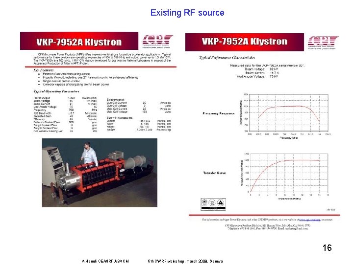
Existing RF source 16 A. Hamdi CEA/IRFU/SACM 5 th CWRF workshop, march 2008, Geneva
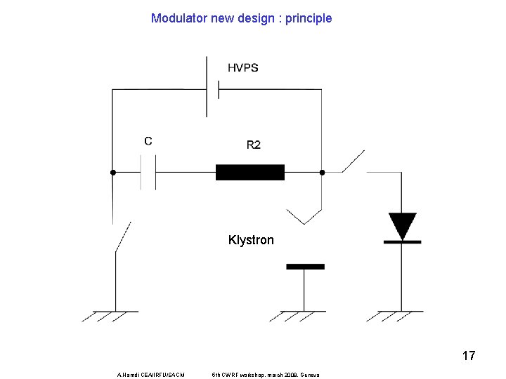
Modulator new design : principle Klystron 17 A. Hamdi CEA/IRFU/SACM 5 th CWRF workshop, march 2008, Geneva
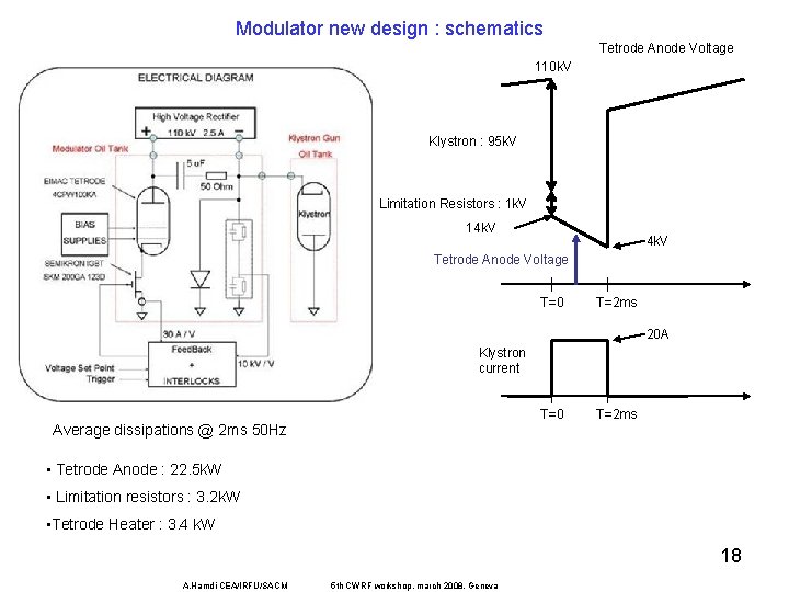
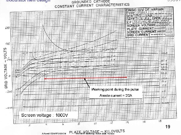
Modulator new design : schematics Tetrode Anode Voltage 110 k. V Klystron : 95 k. V Limitation Resistors : 1 k. V 14 k. V Tetrode Anode Voltage T=0 T=2 ms 20 A Klystron current T=0 Average dissipations @ 2 ms 50 Hz T=2 ms • Tetrode Anode : 22. 5 k. W • Limitation resistors : 3. 2 k. W • Tetrode Heater : 3. 4 k. W 18 A. Hamdi CEA/IRFU/SACM 5 th CWRF workshop, march 2008, Geneva
19 A. Hamdi CEA/IRFU/SACM 5 th CWRF workshop, march 2008, Geneva
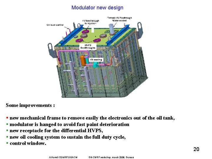
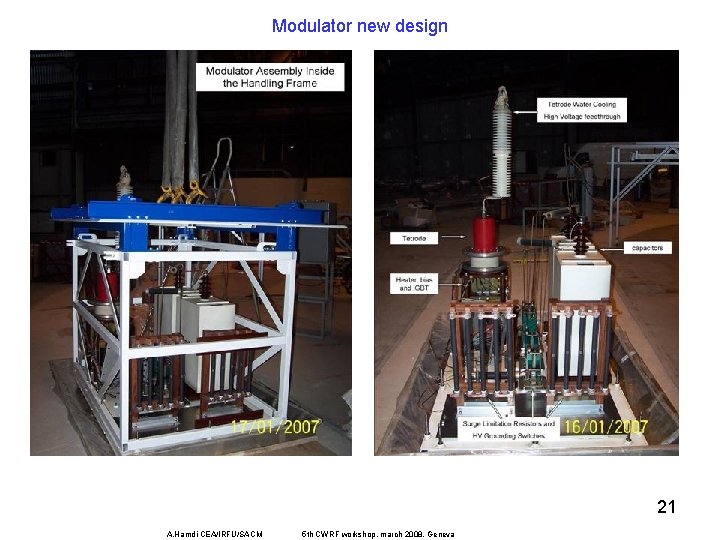
Modulator new design Some improvements : § new mechanical frame to remove easily the electronics out of the oil tank, § modulator is hanged to avoid fast paint deterioration § new receptacle for the differential HVPS, § new oil cooling system to sustain the full duty cycle, § control window. 20 A. Hamdi CEA/IRFU/SACM 5 th CWRF workshop, march 2008, Geneva
Modulator new design 21 A. Hamdi CEA/IRFU/SACM 5 th CWRF workshop, march 2008, Geneva
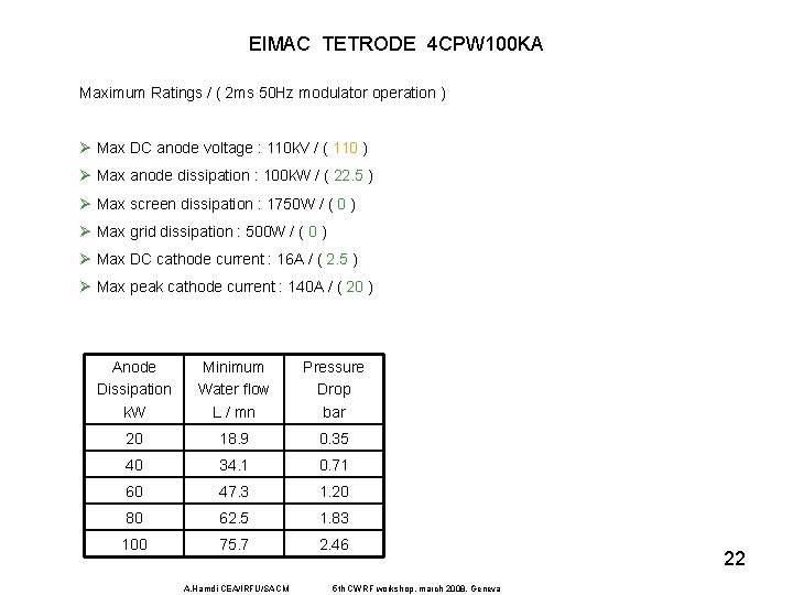
EIMAC TETRODE 4 CPW 100 KA Maximum Ratings / ( 2 ms 50 Hz modulator operation ) Ø Max DC anode voltage : 110 k. V / ( 110 ) Ø Max anode dissipation : 100 k. W / ( 22. 5 ) Ø Max screen dissipation : 1750 W / ( 0 ) Ø Max grid dissipation : 500 W / ( 0 ) Ø Max DC cathode current : 16 A / ( 2. 5 ) Ø Max peak cathode current : 140 A / ( 20 ) Anode Dissipation k. W Minimum Water flow L / mn Pressure Drop bar 20 18. 9 0. 35 40 34. 1 0. 71 60 47. 3 1. 20 80 62. 5 1. 83 100 75. 7 2. 46 A. Hamdi CEA/IRFU/SACM 5 th CWRF workshop, march 2008, Geneva 22
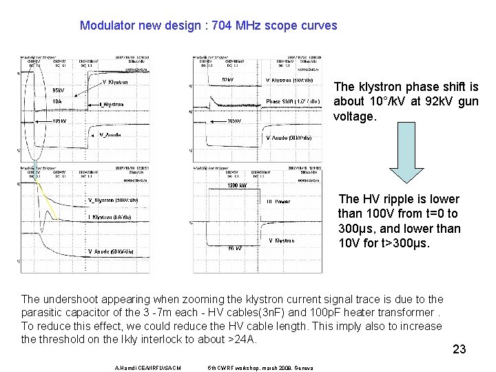
Modulator new design : 704 MHz scope curves The klystron phase shift is about 10°/k. V at 92 k. V gun voltage. The HV ripple is lower than 100 V from t=0 to 300µs, and lower than 10 V for t>300µs. The undershoot appearing when zooming the klystron current signal trace is due to the parasitic capacitor of the 3 -7 m each - HV cables(3 n. F) and 100 p. F heater transformer. To reduce this effect, we could reduce the HV cable length. This imply also to increase threshold on the Ikly interlock to about >24 A. A. Hamdi CEA/IRFU/SACM 5 th CWRF workshop, march 2008, Geneva 23
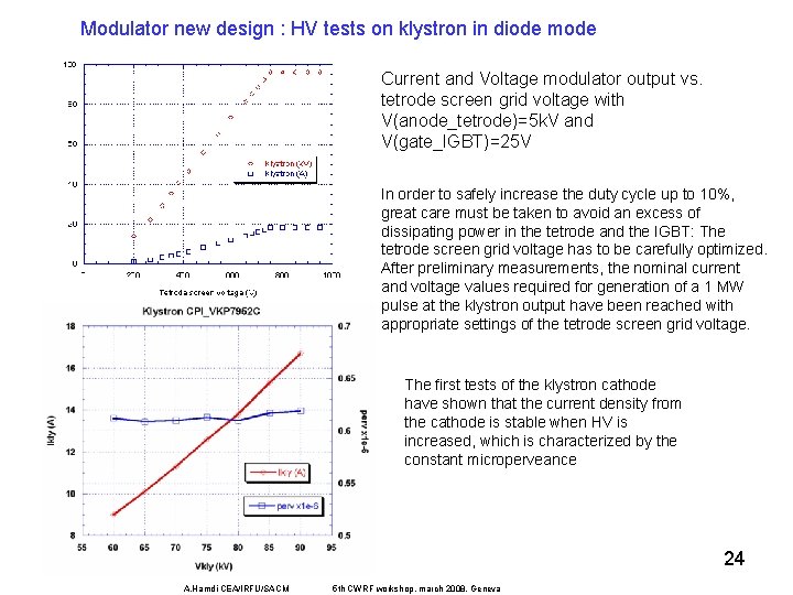
Modulator new design : HV tests on klystron in diode mode Current and Voltage modulator output vs. tetrode screen grid voltage with V(anode_tetrode)=5 k. V and V(gate_IGBT)=25 V In order to safely increase the duty cycle up to 10%, great care must be taken to avoid an excess of dissipating power in the tetrode and the IGBT: The tetrode screen grid voltage has to be carefully optimized. After preliminary measurements, the nominal current and voltage values required for generation of a 1 MW pulse at the klystron output have been reached with appropriate settings of the tetrode screen grid voltage. The first tests of the klystron cathode have shown that the current density from the cathode is stable when HV is increased, which is characterized by the constant microperveance 24 A. Hamdi CEA/IRFU/SACM 5 th CWRF workshop, march 2008, Geneva
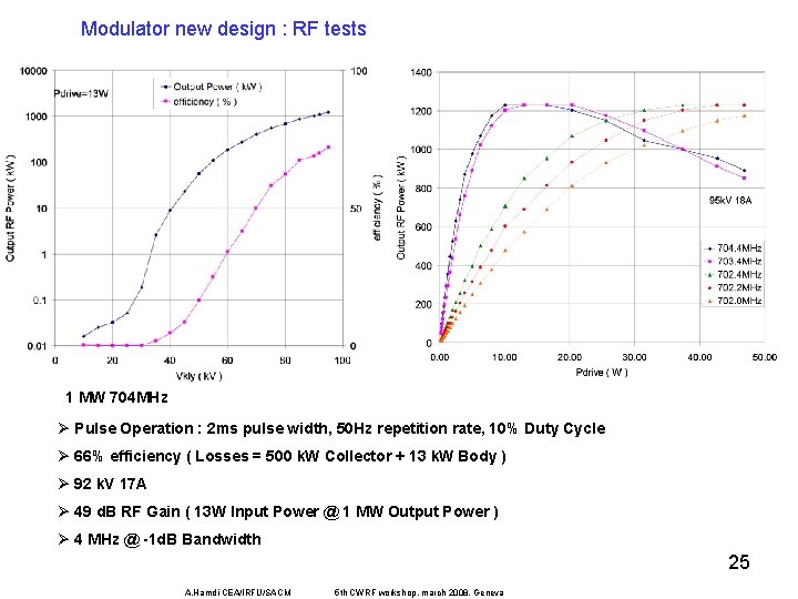
Modulator new design : RF tests 1 MW 704 MHz Ø Pulse Operation : 2 ms pulse width, 50 Hz repetition rate, 10% Duty Cycle Ø 66% efficiency ( Losses = 500 k. W Collector + 13 k. W Body ) Ø 92 k. V 17 A Ø 49 d. B RF Gain ( 13 W Input Power @ 1 MW Output Power ) Ø 4 MHz @ -1 d. B Bandwidth 25 A. Hamdi CEA/IRFU/SACM 5 th CWRF workshop, march 2008, Geneva
Summary of Modifications q modulator tank : • oil cooling connections • one more HV feedthrough • Limitation resistors dissipation upgrade • 300 H choke removal q new High Voltage Power Supply with two poles isolated at full rated voltage q auxiliary power supplies : • klystron focusing coils • klystron ion pump • klystron heater • interlocks q klystron water cooling 26 A. Hamdi CEA/IRFU/SACM 5 th CWRF workshop, march 2008, Geneva
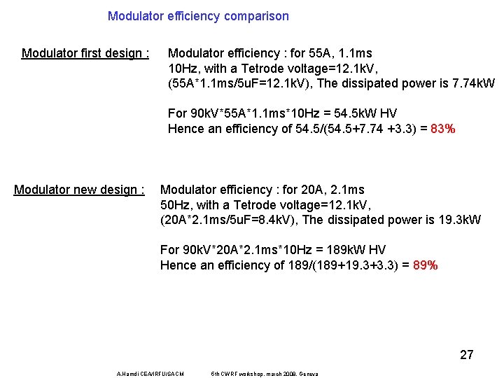
Modulator efficiency comparison Modulator first design : Modulator efficiency : for 55 A, 1. 1 ms 10 Hz, with a Tetrode voltage=12. 1 k. V, (55 A*1. 1 ms/5 u. F=12. 1 k. V), The dissipated power is 7. 74 k. W For 90 k. V*55 A*1. 1 ms*10 Hz = 54. 5 k. W HV Hence an efficiency of 54. 5/(54. 5+7. 74 +3. 3) = 83% Modulator new design : Modulator efficiency : for 20 A, 2. 1 ms 50 Hz, with a Tetrode voltage=12. 1 k. V, (20 A*2. 1 ms/5 u. F=8. 4 k. V), The dissipated power is 19. 3 k. W For 90 k. V*20 A*2. 1 ms*10 Hz = 189 k. W HV Hence an efficiency of 189/(189+19. 3+3. 3) = 89% 27 A. Hamdi CEA/IRFU/SACM 5 th CWRF workshop, march 2008, Geneva
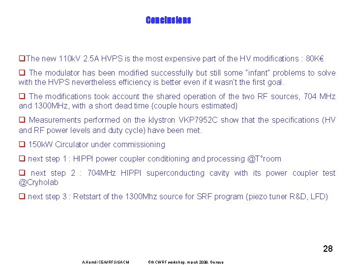
Conclusions q. The new 110 k. V 2. 5 A HVPS is the most expensive part of the HV modifications : 80 K€ q The modulator has been modified successfully but still some “infant” problems to solve with the HVPS nevertheless efficiency is better even if it wasn’t the first goal. q The modifications took account the shared operation of the two RF sources, 704 MHz and 1300 MHz, with a short dead time (couple hours estimated) q Measurements performed on the klystron VKP 7952 C show that the specifications (HV and RF power levels and duty cycle) have been met. q 150 k. W Circulator under commissioning q next step 1 : HIPPI power coupler conditioning and processing @T°room q next step 2 : 704 MHz HIPPI superconducting cavity with its power coupler test @Cryholab q next step 3 : Retstart of the 1300 Mhz source for SRF program (piezo tuner R&D, LFD) 28 A. Hamdi CEA/IRFU/SACM 5 th CWRF workshop, march 2008, Geneva
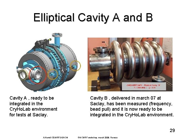
Elliptical Cavity A and B • Cavity A , ready to be integrated in the Cry. Ho. Lab environment for tests at Saclay. Cavity B , delivered in march 07 at Saclay, has been measured (frequency, bead pull) and it is now ready to be integrated in the Cry. Ho. Lab environment. 29 A. Hamdi CEA/IRFU/SACM 5 th CWRF workshop, march 2008, Geneva
30 A. Hamdi CEA/IRFU/SACM 5 th CWRF workshop, march 2008, Geneva
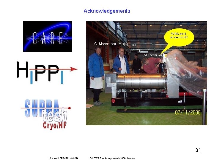
Acknowledgements 31 A. Hamdi CEA/IRFU/SACM 5 th CWRF workshop, march 2008, Geneva
References • M. Desmons, “Cryholab modulator modifications for HIPPI 704 MHz 1 MW pulsed RF source”, HIPPI -WP 3 meeting - march 2005, LASA / INFN – Milan • S. Chel, M. Desmons, A. Hamdi, J. -F. Denis, F. Ballester, D. Roudier, G. Monnereau, G. Bourdelle, “ 1 MW - 704 MHz RF test stand at CEA-Saclay”, CARE deliverable November 2007 • G. Devanz, “HIPPI 704 MHz Power Coupler” - HIPPI WP 3/5 meeting Juelich 27 Apr 06 32 A. Hamdi CEA/IRFU/SACM 5 th CWRF workshop, march 2008, Geneva
Vielen Danke ! Merci de votre attention! Thank you ! Questions in French or Moroccan please? A. Hamdi CEA/IRFU/SACM 5 th CWRF workshop, march 2008, Geneva 33