CAN Controller Area Network 29 BIT ID Overview

CAN Controller Area Network 29 BIT ID Overview and Application Timothy E. Jackson

CAN Frame

CAN Frame IDENTIFIER DLC DATA FIELD Identifier = 29 bits + MAC DLC = Data Length Code 4 bits Indicates number of data bytes Data Field = 0 to 7 bytes Depends on the DLC value

CAN Frame CRC delimiter Standard Format, 2. 0 A 1 bit Max frame length with bit stuffing = 127 bits S O F Arbitration Field Control Field Data Field 12 bits 6 bits 0 to 64 bits Identifier 11 bits R T R I D E r 0 DLC 4 bits Data Field CRC 15 bits ACK Field 2 bits No Bit Stuffing SOF = Start Of Frame RTR = Remote Transmission Request IDE = Identifier Extension Bit DLC = Data Length Code CRC = Cyclic Redundancy Check ACK = Acknowledgement EOF = End Of Frame EOF 7 bits

CAN Frame CRC delimiter Extended Format, 2. 0 B 1 bit Max frame length with bit stuffing = 150 bits S O F Identifier 11 bits Arbitration Field Control Field Data Field 32 bits 6 bits 0 to 64 bits SRR IDE Identifier Ext. 18 bits RTR r 1 r 2 DLC 4 bits Data Field CRC 15 bits ACK Field 2 bits No Bit Stuffing SOF = Start Of Frame SRR = Substitute Remote Request IDE = Identifier Extension Bit RTR = Remote Transmission Request DLC = Data Length Code CRC = Cyclic Redundancy Check ACK = Acknowledgement EOF = End Of Frame EOF 7 bits

CAN Frame CRC delimiter 1 bit S O F Identifier 11 bits Arbitration Field Control Field Data Field 32 bits 6 bits 0 to 64 bits SRR IDE Identifier Ext. 18 bits RTR r 1 r 2 DLC 4 bits Data Field CRC 15 bits ACK Field 2 bits EOF 7 bits

CAN Frame Message Structure PRI 29 Bit Identifier DLC DATA FIELD 29 bits 4 bits 0 to 8 bytes PGN SA PRI= Priority 3 bits PGN = Parameter Group Number, 18 bits SA = Source Address, 8 bits

How do I start using CAN right now? • SAE J 1939 – Defined by the automotive industry – Standards defined for the Layers 1, 2, 3, 4, and 7

ISO Layers according to SAE J 1939 Layer 7 Application Layer 6 Presentation Layer 5 Session Layer 4 Transport Layer 3 Network Layer 2 Data Link Layer 1 Physical Layer SAE J 1939/71 SAE J 1939/73 SAE J 1939/21 SAE J 1939/31 SAE J 1939/21 SAE J 1939/12

ISO Layers Used In EAMCS Layer 7 Application Layer 2 Data Link Layer 1 Physical Layer

Physical Layer SAE J 1939/11 – High Speed Bus Connection • Differential signal transmission • Shielded twisted pair bus lines and ground • 250 k bits/sec • 30 nodes max. • Bus length = 40 m max. or 131 ft. max. SAE J 1939/12 – Variant Bus Connection • Bus constructed using active termination For bus load = 1 (Using 29 bit ID and 8 data bytes per frame, approx. 135 bits/message) At a bitrate of 250 kbps 1850 messages per second
 120Ω Node B (UQM Inverter) 120Ω")
Node A (EAMCS) 120Ω Node B (UQM Inverter) 120Ω

Example MSCAN Timing
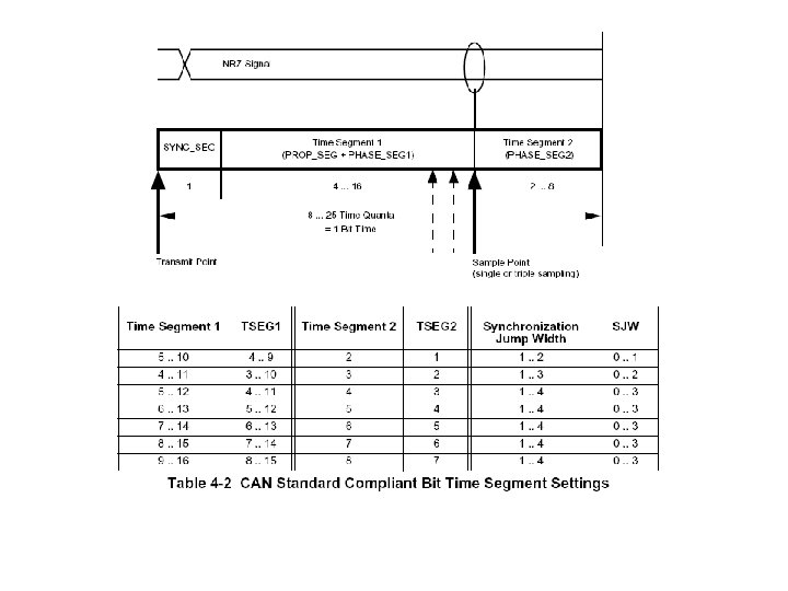

Cont. Example MSCAN Timing 16 Tq = SYNC_SEG + Propagation. Delay. Seg + Time. Seg 1 + Time. Seg 2 SYNC_SEG = 1 Tq Propagation. Delay. Seg = 2 Tq (Determined by bus characteristics) Pick, Time. Seg 2 = 5 Tq Time. Seg 1 = 8 Tq This gives a SJW range 0… 3 so, I picked 2 Once values are determined, then apply to MSCAN registers

Data Link Layer SAE J 1939/21 29 Bit ID PRI PGN SA 28… 26 25 24 23… 16 15… 8 7… 0 PRI r DP PF DA/GE SA PRI= Priority 3 bits PGN = Parameter Group Number, 18 bits r = Reserved Bit, always 0 or dominant DP = Data Page PF = PDU format, (Protocol Data Unit) DA = Destination Address GE = Group Extension SA = Source Address, 8 bits

Example: EAMCS Message sent to UQM Inverter 29 Bit ID PRI r DP PDU Dest. Addr Source Addr 28… 26 25 24 23… 16 15… 8 7… 0 0 x 06 0 x 04 0 0 0 x. EF 0 x 02 0 x 01 Priority Defined by SAE Reserved for future use Defined by SAE PDU DA SA Defined by SAE Defined by User

Application Layer SAE J 1939/71 Defines the bytes in the data field

SAE HANDBOOK DATA

Example: Parameter Group Definition Electric Drive State • • • Transmission Repetition Rate: 100 ms Data Length: 8 bytes Byte Data Page: 0 PDU format: 239 1 PDU specific: DA 2, 3 Default Priority: 4 4 Definitions Command 0 x 10 Actual Speed Torque 5 Voltage 6 Current 7, 8 System Error

Cont. Example: Parameter Group Definition Byte 1 2, 3 Definitions Command 0 x 10 Actual Speed 4 Torque 5 Voltage 6 Current 7, 8 System Error Definitions Command Byte 1 Data Field Actual Speed Byte 2 Byte 3 Torque Voltage Current Byte 4 Byte 5 Byte 6 System Error Byte 7 Byte 8
 Define a struct typedef")
Cont. Example: Parameter Group Decoding Using MSCAN (The Easy Way) Define a struct typedef struct{ INT 8 U command; INT 16 U actual_speed; INT 8 U torque; INT 8 U voltage; INT 8 U current; INT 16 U system_error; }ELEC_DRIVE_STATE; CANRXFG[4] Command D Actual Speed (MSB) a Actual Speed (LSB) t Torque Create an Instance ELEC_DRIVE_STATE elec_drive_data; F Voltage i Current e System Error (MSB) l System Error (LSB) d Take advantage of Struct copying routines elec_drive_data = *(ELEC_DRIVE_STATE*)(CANRXFG + 4); Now access the data fields using the corresponding struct member outhexw(&elec_drive_data. actual_speed); a /* Print the 16 bit hex value */

References Motorola Documentation MSCAN Block Guide V 02. 14, S 12 MSCANV 2. pdf Bosch Documentation CAN Specification Version 2. 0, can 2 spec. pdf Reference Texts Konrad Etschberger, Controller Area Network. Weingarten, Germany: IXXAT Automation Gmb. H, 2001 1997 SAE Handbook, Volume 2 Parts and Components. Warrendale, PA: Society of Automotive Engineers, 1997
- Slides: 23