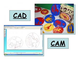
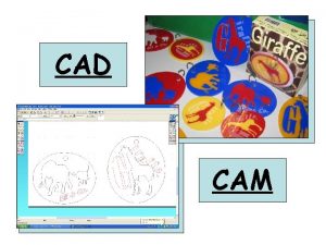
CAD CAM Automation WHAT IS CAD CADD CAD


- Slides: 12

CAD CAM Automation

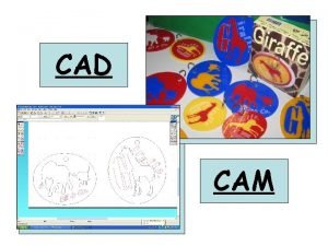
WHAT IS CAD & CADD • CAD – Computer Aided Drafting. • CADD – Computer Aided Designing & Drafting.

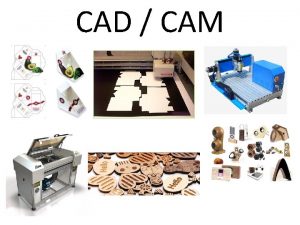
CAM • CAM - Computer Aided Manufacturing – NC Part Programming for machining and other processing applications.

CAE • CAE- Computer Aided Engineering – Error Checking – Analysis – Optimization – Manufacturability of the product design.

• CAPP – Computer Aided Process Planning • CATD – Computer Aided Tool Design • CAP – Computer Aided Planning

Why Computers are Used in Manufaturing • Short lead time • Short Product Lives • Increasing Consumer Awareness regarding the quality of the Product

Unit: 1 • COMPUTER GRAPHICS • Computer Graphics Module, Transformations -Introduction, Formulation, Translation, Rotation, Scaling and Reflection. • Homogenous Representation, Concatenated Transformation, Mapping of Geometric • Models, Inverse Transformations. Projections: Orthographic and Isometric.

Unit: 2 • Modelling • Curves-Introduction, Analytic Curves - Line, Circle, Ellipse, Parabola, Hyperbola. Synthetic Curves • Hermite Cubic Spline, Bezier Curve, B-Spline Curve. Numerical on Line, Circle, Ellipse and Hermite • Cubic Spline • Surfaces-Introduction, Surface Representation, Analytic Surfaces, Synthetic Surfaces, Hermite bicubic • Surface, Bezier surfaces, B-spline Surfaces, Coons Surface [No analytical treatment]. • Solids: Introduction, Geometry and Topology, Solid Representation, Boundary Representation, Euler's • equation, Constructive Solid Geometry, Boolean operation for CSG, Hybrid Modeling, Feature Based • Modeling, Parametric Modeling, Constraint Based Modeling, Mass, area, volume calculation.

Unit: 3 • FINITE ELEMENT ANALYSIS • Introduction, Stress and Equilibrium, Boundary Condition, Strain – Displacement Relations, Stress • Strain Relation, Potential Energy and Equilibrium: Rayleigh-Ritz Method, Galerkin‘s Method. • One Dimensional Problem: Finite Element Modelling, Coordinate and Shape function, Potential Energy • Approach, Galerkin Approach, Assembly of Global Stiffness Matrix and Load Vector, Properties of • Stiffness Matrix, Finite Element Equations, Quadratic Shape Function, Temperature Effects. • Trusses: Introduction, 2 D Trusses, Assembly of Global Stiffness Matrix.

Unit 4 Computer Aided Manufacturing • Introduction to Computer Aided Manufacturing. CNC Programming-CNC part programming adaptable • to FANUC controller. Steps in developing CNC part programming for Lathe • Machine – Threading & Grooving cycle(Canned cycle). CNC part programming for Milling Machine • Linear & circular interpolation, milling cutter, tool length compensation & cutter radius compensation. • Pocketing, contouring & drilling, subroutine and Do loop using canned cycle.

Unit 5 • Advanced Manufacturing Method – Rapid Prototyping • Introduction to Rapid Prototyping, classification of RP Processes, Working principle, models & • specification process, application, advantages & disadvantages & case study of • Stereo Lithography Apparatus (SLA) • Laminated Object Manufacturing (LOM) • Selective Laser Sintering (SLS) • 3 D Printing. • Fused Deposition Modeling [FDM] • Rapid Tolling and STL format.

Unit 6 • Robotics & Automation • Structure of Robotic System - Point to point & continuous path robotic systems, Joints, End Effectors, • Grippers - Mechanical, Magnetic and Pneumatic. Drives, Controllers, Industrial Applications. • Types of Automation - Automation strategies, Group Technology & Coding Methods, Flexible • Manufacturing System – Types, Advantages, Limitations. Computer Integrated Manufacturing and • Computer Aided Process Planning.
