AnNajah National University Faculty Of Engineering Telecommunication Engineering

- Slides: 32
An-Najah National University Faculty Of Engineering Telecommunication Engineering Department Millimeter Wave Massive MIMO For Next Generation Wireless Communication Supervisor: Dr. Yousef Dama Prepared By: Asma’a Halbouni Asma’a Yaish
Outline v v v v Introduction, Standard And Constraints. Massive MIMO System. Alamouti Code. QO-STBC. Millimeter Wave. NYUSIM. S-V Model. Conclusion.
Introduction: �The development and growth of wireless technologies in the past decade has led to the rapid adoption of smart phones. Consumers are expecting every device they have to be connected to the network. So that, the spectrum available for these devices will not be enough. �Utilizing unused mm. Wave spectrum is one key enabling solution for meeting the extreme data demand growth. �While mm. Wave spectrum offers a great opportunity to increase capacity, little is known about the propagation channel characteristics.
Channel Characteristic �There have been intensive investigations on mm. Wave propagation characteristics in various environments. �The construction and implementation of channel models such as channel simulators are essential for performance evaluation of communications systems, before moving forward with new technologies, such as NYUSIM for outdoor environment.
Standard And Constraints �Standard: 5 G simply stands for fifth generation, where its standard is yet to be set. �Constraints: mm. Wave due to its high frequency it suffer from small wavelength, which means small distance. Ø Lack of frequency and spectrum. Ø
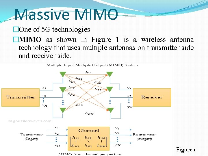
Massive MIMO �One of 5 G technologies. �MIMO as shown in Figure 1 is a wireless antenna technology that uses multiple antennas on transmitter side and receiver side. Figure 1
Massive MIMO �Between transmitter and receiver, the signal can take many paths. Previously these multiple paths only served to introduce interference (ISI). �By using MIMO, these additional paths can be used to provide additional robustness to the radio link by improving the bit error rate, or by increasing the link data capacity. �Massive MIMO in which number of transmitter antenna is more 64.
�MIMO Gain There are two main formats for MIMO system: v Diversity gain (Spatial Diversity): Equal to the number of independent channels in the system. Which will also in other words increase data rate. v Multiplexing Gain (Spatial Multiplexing): will serve the main purpose for increasing capacity by utilizing the multiple paths as additional channels to carry data.
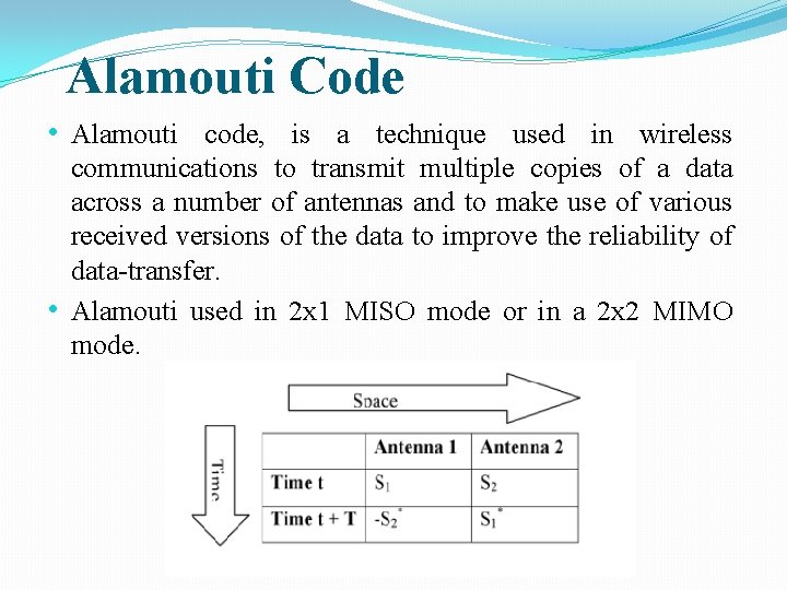
Alamouti Code • Alamouti code, is a technique used in wireless communications to transmit multiple copies of a data across a number of antennas and to make use of various received versions of the data to improve the reliability of data-transfer. • Alamouti used in 2 x 1 MISO mode or in a 2 x 2 MIMO mode.
Alamouti And STBC § Alamouti code, the only STBC that can achieve its full diversity gain without needing to sacrifice its data rate. § The information to be transmitted is modulated and fed to the space time encoder, which consists of two transmit antennas. § Each Tx-Rx pair has a channel, represented by different channel coefficients.
Quasi-Orthogonal Space Time Block Coding (QO-STBC) § To achieve full-rate transmission while maintaining much of the orthogonality benefits of OSTBC, (QO-STBC) has been proposed. § A QO-STBC can achieve full rate, but interference terms will appear from the neighboring signals during the signal detection which will increase the detection complexity and decrease the gain performance.
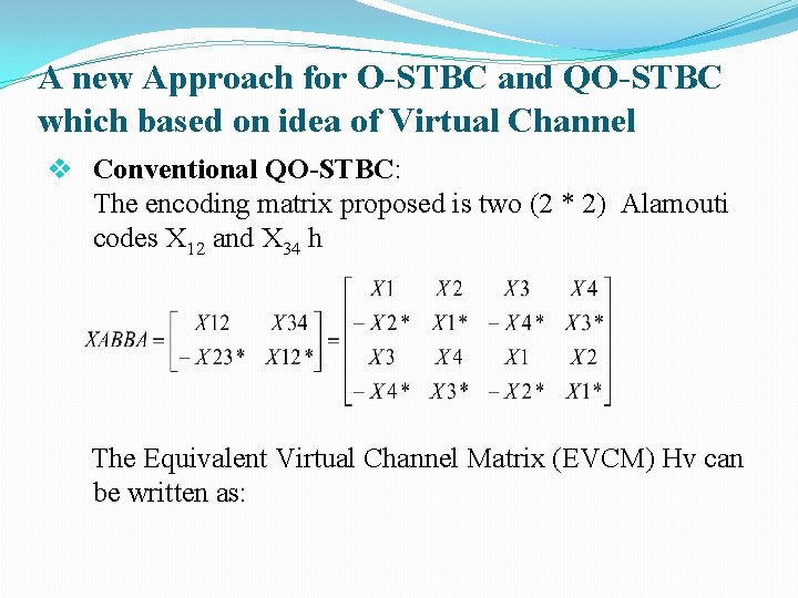
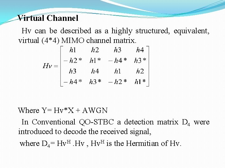
A new Approach for O-STBC and QO-STBC which based on idea of Virtual Channel v Conventional QO-STBC: The encoding matrix proposed is two (2 * 2) Alamouti codes X 12 and X 34 h The Equivalent Virtual Channel Matrix (EVCM) Hv can be written as:
Virtual Channel Hv can be described as a highly structured, equivalent, virtual (4*4) MIMO channel matrix. Where Y= Hv*X + AWGN In Conventional QO-STBC a detection matrix D 4 were introduced to decode the received signal, where D 4= Hv. H. Hv , Hv. H is the Hermitian of Hv.
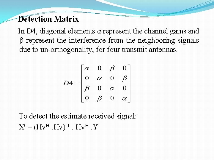
Detection Matrix In D 4, diagonal elements α represent the channel gains and represent the interference from the neighboring signals due to un-orthogonality, for four transmit antennas. To detect the estimate received signal: X' = (Hv. H. Hv)-1. Hv. H. Y
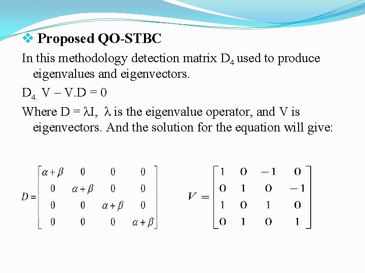
v Proposed QO-STBC In this methodology detection matrix D 4 used to produce eigenvalues and eigenvectors. D 4. V – V. D = 0 Where D = λI, λ is the eigenvalue operator, and V is eigenvectors. And the solution for the equation will give:
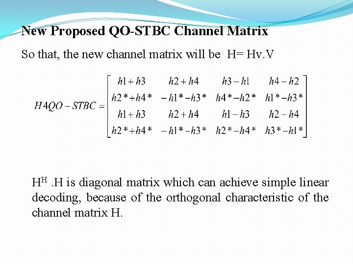
New Proposed QO-STBC Channel Matrix So that, the new channel matrix will be H= Hv. V HH. H is diagonal matrix which can achieve simple linear decoding, because of the orthogonal characteristic of the channel matrix H.
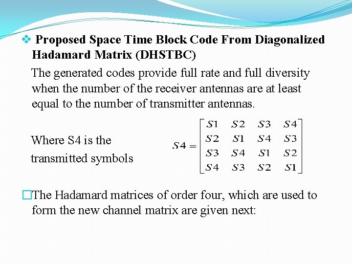
v Proposed Space Time Block Code From Diagonalized Hadamard Matrix (DHSTBC) The generated codes provide full rate and full diversity when the number of the receiver antennas are at least equal to the number of transmitter antennas. Where S 4 is the transmitted symbols �The Hadamard matrices of order four, which are used to form the new channel matrix are given next:
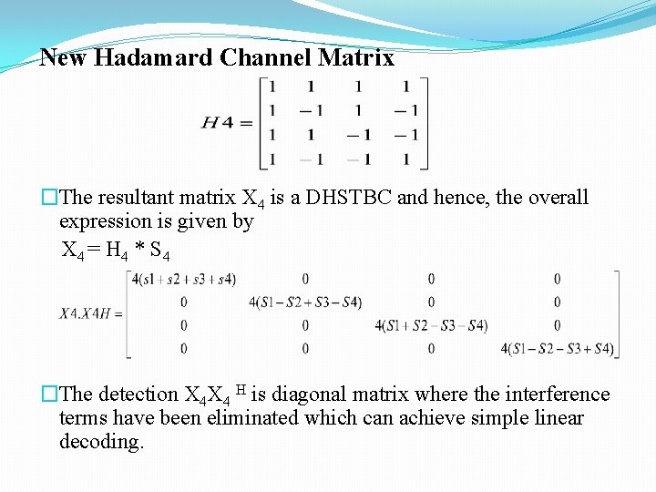
New Hadamard Channel Matrix �The resultant matrix X 4 is a DHSTBC and hence, the overall expression is given by X 4 = H 4 * S 4 �The detection X 4 X 4 H is diagonal matrix where the interference terms have been eliminated which can achieve simple linear decoding.
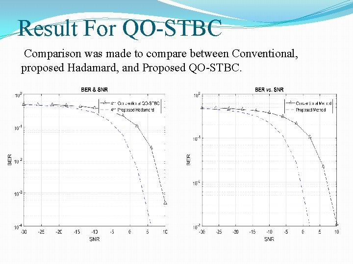
Result For QO-STBC Comparison was made to compare between Conventional, proposed Hadamard, and Proposed QO-STBC.
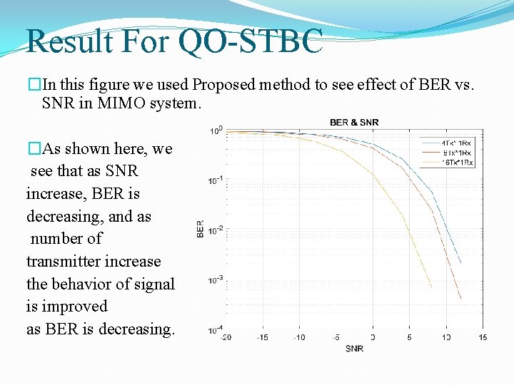
Result For QO-STBC �In this figure we used Proposed method to see effect of BER vs. SNR in MIMO system. �As shown here, we see that as SNR increase, BER is decreasing, and as number of transmitter increase the behavior of signal is improved as BER is decreasing.
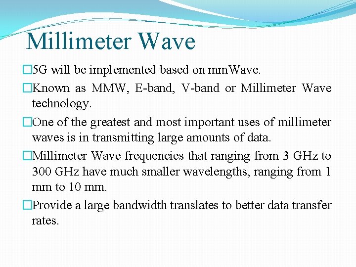
Millimeter Wave � 5 G will be implemented based on mm. Wave. �Known as MMW, E-band, V-band or Millimeter Wave technology. �One of the greatest and most important uses of millimeter waves is in transmitting large amounts of data. �Millimeter Wave frequencies that ranging from 3 GHz to 300 GHz have much smaller wavelengths, ranging from 1 mm to 10 mm. �Provide a large bandwidth translates to better data transfer rates.
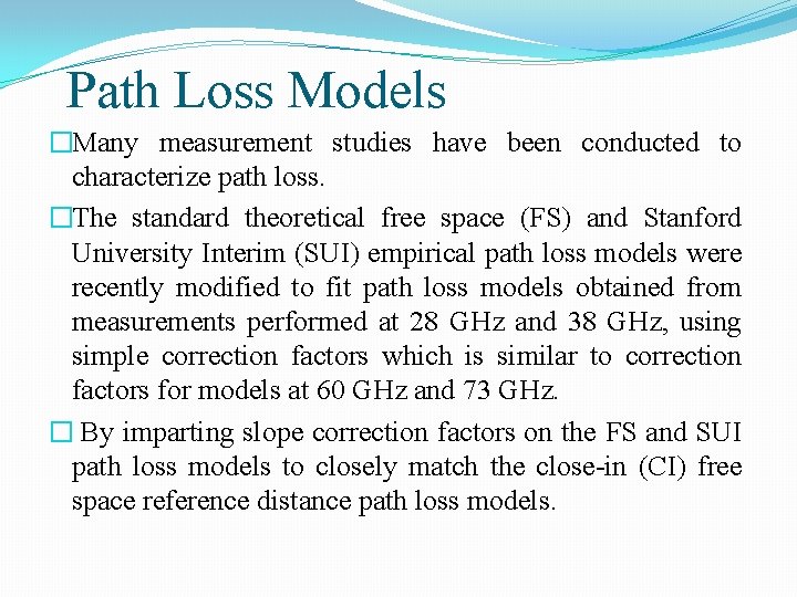
Path Loss Models �Many measurement studies have been conducted to characterize path loss. �The standard theoretical free space (FS) and Stanford University Interim (SUI) empirical path loss models were recently modified to fit path loss models obtained from measurements performed at 28 GHz and 38 GHz, using simple correction factors which is similar to correction factors for models at 60 GHz and 73 GHz. � By imparting slope correction factors on the FS and SUI path loss models to closely match the close-in (CI) free space reference distance path loss models.
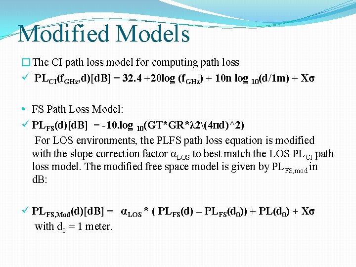
Modified Models �The CI path loss model for computing path loss ü PLCI(f. GHz, d)[d. B] = 32. 4 +20 log (f. GHz) + 10 n log 10(d/1 m) + Xσ • FS Path Loss Model: ü PLFS(d)[d. B] = -10. log 10(GT*GR*λ 2(4 пd)^2) For LOS environments, the PLFS path loss equation is modified with the slope correction factor αLOS to best match the LOS PLCI path loss model. The modified free space model is given by PLFS, mod in d. B: ü PLFS, Mod(d)[d. B] = αLOS * ( PLFS(d) – PLFS(d 0)) + PL(d 0) + Xσ with d 0 = 1 meter.
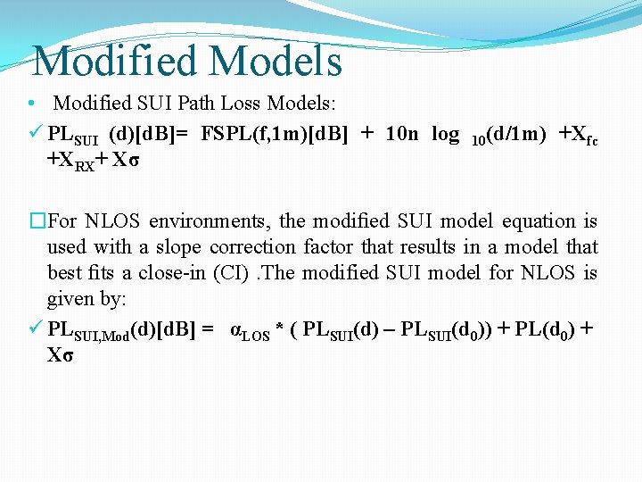
Modified Models • Modified SUI Path Loss Models: ü PLSUI (d)[d. B]= FSPL(f, 1 m)[d. B] + 10 n log +XRX+ Xσ 10(d/1 m) +Xfc �For NLOS environments, the modified SUI model equation is used with a slope correction factor that results in a model that best fits a close-in (CI). The modified SUI model for NLOS is given by: ü PLSUI, Mod(d)[d. B] = αLOS * ( PLSUI(d) – PLSUI(d 0)) + PL(d 0) + Xσ
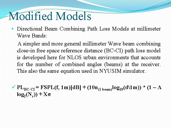
Modified Models • Directional Beam Combining Path Loss Models at millimeter Wave Bands: A simpler and more general millimeter Wave beam combining close-in free space reference distance (BC-CI) path loss model is developed here for NLOS urban environments that accounts for the number of combined angles (beams) at the receiver. This also the same equation used in NYUSIM simulator. ü PLBC-CI = FSPL(f, 1 m)[d. B] + (10 n(1 beam)log 10(d1 m)) * (1 – A log 2(Nr)) + Xσ
NYUSIM simulator �Wireless communication systems developed by researchers at New York University (NYU). �Channel simulation software named NYUSIM, can be used to generate realistic temporal and spatial channel responses to support realistic. � NYUSIM is built upon channel model for broadband millimeter-wave(mm. Wave).
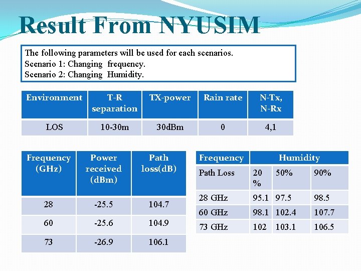
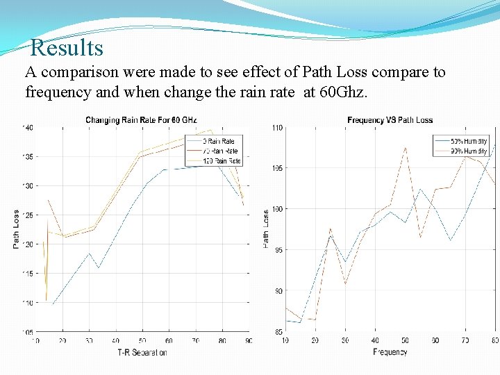
Result From NYUSIM The following parameters will be used for each scenarios. Scenario 1: Changing frequency. Scenario 2: Changing Humidity. Environment T-R separation TX-power Rain rate N-Tx, N-Rx LOS 10 -30 m 30 d. Bm 0 4, 1 Frequency (GHz) Power received (d. Bm) Path loss(d. B) 28 -25. 5 104. 7 60 -25. 6 104. 9 73 -26. 9 106. 1 Frequency Humidity Path Loss 20 % 50% 90% 28 GHz 95. 1 97. 5 98. 5 60 GHz 98. 1 102. 4 107. 7 73 GHz 102 103. 1 106. 5
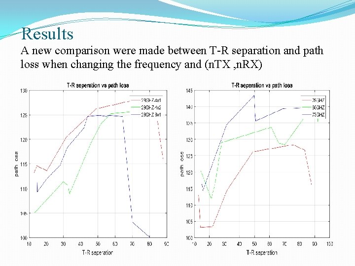
Results A new comparison were made between T-R separation and path loss when changing the frequency and (n. TX , n. RX)
Results A comparison were made to see effect of Path Loss compare to frequency and when change the rain rate at 60 Ghz.
Saleh -Valenzuela (S-V) Channel Model �S-V model is based on a clustering phenomenon observed in experimental data. Saleh and Valenzuela found from the indoor channel. � As SNR increase, BER will decrease and increasing number of transmitter and receiver will reduce BER.
Conclusion �Studied concept of mm. Wave, and Massive MIMO. �A new approach for QO-STBC for four transmitter antennas, based on Virtual channel �Detection matrix in Proposed method to eliminate the interference terms. � Modified Models and NSYUSIM. �S-V Model
Future Work Studying the other technologies of 5 G: ü Massive MIMO. ü Beamforming. ü Spatial Modulation.