Activity Diagrams Elements Activity without partitions nitial node

 � nitial node: Indicates where the workflow begins. � Control")


 � The elements in an activity diagram can be")
- Slides: 11
Activity Diagrams
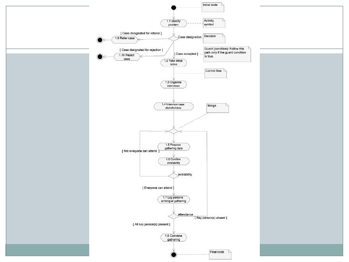
Elements (Activity without partitions) � nitial node: Indicates where the workflow begins. � Control flow: An arrow showing the direction of the workflow. � Activity: Indicates a step in the process. � Decision: A diamond symbol, indicating a choice. Workflow will proceed along one of a number of possible paths, according to the guard conditions. � Merge: Use this symbol if you wish to adhere to strictly to the UML standard when modeling a number of alternative flows that lead to the same activity. Rather than terminating them at the same activity, terminate them at a merge, and draw a flow from the merge to the activity. For business-analysis purposes, however, you might want to consider relaxing the standard by dispensing with the merge as it does hinder readability.
� Guard condition: A condition attached to a control flow. When the guard condition is true, workflow may flow along the control flow. Guard conditions are usually attached to control flows that come out of a decision symbol. (However, they can also be used without the decision symbol. ) A guard is shown within square brackets. � Event: A trigger attached to a control flow. The event must occur for the flow to move along the control flow. Declaring something as an event has a stronger implication than calling it a guard. An event actually triggers the control flow by forcing the previous activity to end, whereas a guard only governs whether a flow that was triggered for another reason (such as the completion of the previous activity) is allowed to flow along the control flow. An event is indicated without the use of square brackets.
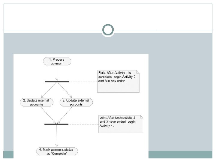
� Fork and join: Bars used to document parallel activities. In the UML, parallel activities are those that may begin in any sequence—either at the same time or one before the other. A fork indicates the point after which a number of activities may begin in any order. A join indicates that workflow may commence only once the parallel activities that flow into it have all been completed. � Final node: Indicates the end of the process.
A control flow labeled with an event
Activities nested within an activity symbol.
Objects Flow � If you find the preceding notation communicates enough about a workflow to stakeholders, you won’t need the extra notations described next. But the UML does give you the option of indicating the inputs and outputs of any activity on the diagram by adding object flows. (If you are a reader versed in structured analysis, it may help to think of object flows as the UML equivalent of the data flows in a data-flow diagram. ) � Add object flows to your activity diagrams if you wish to show the point at which business objects are created, changed, or required by activities. Examples of business objects that you might think of including in this way are claims, complaints, reports, invoices, and paychecks. On the activity diagram, you will not only be able to identify the object, but you can also indicate what state it’ll be in at that point.
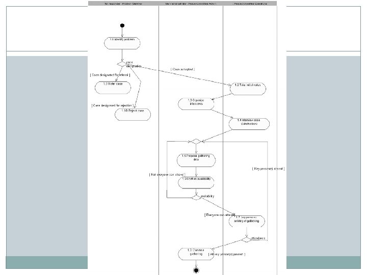
Activity Diagram with Partitions (Swimlanes) � The elements in an activity diagram can be grouped by using partitions. The purpose of a partition is to indicate where the responsibility lies for performing specific activities. In a business model, the partitions may be business units, divisions, or organizations. For systems, the partitions may be other systems or subsystems. In application modeling, the partitions may be objects in the application. Each partition may be named to indicate the responsible party. Figure 5– 31 shows how the various activities. � To indicate who performs each activity, you add partitions (commonly referred to as swimlanes) to the activity diagram. A partition is depicted as a column (or row) on an activity diagram. Allocate one partition for each object that takes an active part in the process flow. Each partition represents a stakeholder (business actor or worker) who carries out some activity. Although you shouldn’t spend too much time focusing on technology at this time, you may also show a computer system as a partition. � Position every activity in the partition of the object that performs it. Name each partition at the top of the column, according to the participating object. You may use an informal, simple name for the partition, identifying the actor who carries out the task.