300 Hz Linac Hardware Upgrade Hardware Upgrade Due


- Slides: 24
300 Hz Linac Hardware Upgrade (Hardware Upgrade ? ? ? Due to present Budget problem) Posi. Pol 2013 at ANL, 4 -7 September 2013 KEK, Junji Urakawa Contents : 0. Short review of 300 Hz conventional positron source 1. 300 Hz Linac Scheme for Beam Loading Compensation 2. Cost 3. Consideration from the design of NLC positron source 4. Plan for beam loading compensation experiment at ATF 5. Summary
0. Short review of 300 Hz conventional positron source From T. Omori et al. / NIMA 672 (2012) 52– 56 The baseline choice of the ILC positron source is the helical undulator scheme. After accelerating the electron beam in the main linac, it passes a 150 m long helical undulator to create a circularly polarized photon beam, and goes to the interaction point. The photon beam hits the production target and generates electron–positron pairs. The positrons are captured, accelerated to 5 Ge. V, damped, and then accelerated to the collision energy in the main linac. Thus the undulator based positron generation gives interconnection to nearly all sub-systems of the ILC. Following design is the backup for proposed ILC positron source.
Time structure of beam 0<t<264. 45 ns, i=0. 532 A 264. 45<t<362. 85 ns, 0 A 362. 85 ns<t<627. 3 ns, 0. 532 A 627. 3 ns<t<725. 7 ns, 0 A 725. 7 ns<t<990. 15 ns, 0. 532 A is beam loading current.
Bunch by bunch extraction from Damping Ring to make ILC beam train. This is the model for positron target system to confirm the generation of ILC positron beam.
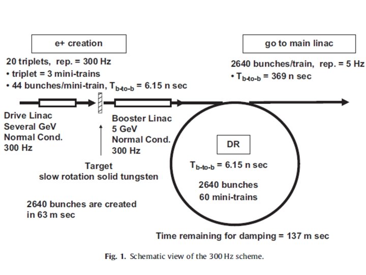
Abstract of the paper. A possible solution to realize a conventional positron source driven by a several-Ge. V electron beam for the International Linear Collider is proposed. A 300 Hz electron linac is employed to create positrons with stretching pulse length in order to cure target thermal load. ILC requires about 2600 bunches in a train which pulse length is 1 ms. Each pulse of the 300 Hz linac creates about 130 bunches, then 2600 bunches are created in 63 ms. Optimized parameters such as drive beam energy, beam size, and target thickness, are discussed assuming a L-band capture system to maximize the capture efficiency and to mitigate the target thermal load. A slow rotating tungsten disk is employed as positron generation target.
1. 300 Hz Linac Scheme for Beam Loading Compensation Phase to Amplitude Modulation Method for Beam Loading Compensation 200 MW, 3 ms 300 Hz Power Supply Low Level RF Phase Shifter and Amp. 80 MW Klystron 3 d. B High Power RF Combiner 50 W High Power Terminator Speed of phase control is about 100 degrees/10 ns.
One accelerator unit for 6 Ge. V Electron Drive Linac Q 0=13000 R 0=60 MOhm
One accelerator unit for 5 Ge. V Positron Linac
3 x 10¹⁰ positron/bunch 300 Hz triplet beam Less than +/- 0. 7% Beam loading current 0. 78 A. 200 MW, 3 ms 300 Hz Power Supply 80 MW Klystron Low Level RF Phase Shifter and Amp. 3 d. B High Power RF Combiner 50 W High Power Terminator We do not need the system of correction structure for beam loading compensation. We need the precise control of the phase shifters. 3 m long constant gradient travelling wave structure Also, I assume 10% margin as wave guide loss and so on because of the experience at ATF Linac. So, klystron output power 80 MW and 3 ms pulse width are necessary.
Control of input RF power by phase shifters Detail of beam loading compensation: Less than ± 0. 7% is possible For ILC 300 Hz multi-bunch beam.
200 MW, 3 ms 12. 5 Hz Power Supply 80 MW Klystron Low Level RF Phase Shifter and Amp. 3 d. B High Power RF Combiner Essential Beam Loading Compensation Scheme 50 W High Power Terminator 3 m long constant gradient travelling wave structure
2. Cost 6 Ge. V Drive Linac with 2 x 10¹⁰ electrons/bunch 38 RF units 2 main klystrons (x 38) with 10% margin and 10% loss 2. 6 GHz 64 MW at RF cavity (total 76 klystrons) 1748 number of 3 m-long cavities (total 76 structures) 1157 2 phase shifters (x 38, total 76 phase shifters) 38 HP combinor (x 38) 130 3 d. B divider (x 38) 70 waveguide (x 38) 20 2 modulators (x 38, total 76 modulators) 3952 Computor Control Unit (x 38) 30 2 correction klystrons x 38 with 10% margin and 10% loss 2. 6 GHz 64 MW at RF cavity (total 76 Klystrons) 1748 number of 0. 33 m long cavities (total 76 structures) 468 2 phase shifters (x 38, total 76 phase shifters) 38 HP combinor (x 38) 130 3 d. B divider (x 38) 70 waveguide (x 38) 20 2 modulators (x 38, total 76 modulators) 3952 Computor Control Unit (x 38) 30 6456 saved 35 quads 35 27 horizontal steerings 10 27 vertical steerings 10 power supplies for magnets 50 beam monitor devices 50 total 13756 26793 M-12571 M= 14222 M, which is 142 Oku-Yen for 300 Hz 6 Ge. V Drive Linac and 5 Ge. V positron Linac.
5 Ge. V Positron Linac with 3 x 10¹⁰ positrons/bunch 36 RF units 2 main klystrons x 36 with 10% margin and 10% loss 2. 6 GHz 64 MW at RF cavity (total 72 Klystrons) 1656 number of 3 m long cavities (total 72 structures) 1096 2 phase shifters (x 36, total 72 phase shifters) 36 HP combinor (x 36) 120 3 d. B divider (x 36) 66 waveguide (x 36) 20 2 modulators (x 36, total 72 modulators) 3744 Computor Control Unit (x 36) 30 2 correction klystrons x 36 with 10% margin and 10% loss 2. 6 GHz 64 MW at RF cavity (total 72 Klystrons) 1656 number of 0. 33 m long cavities (total 72 structures) 443 2 phase shifters (x 36, total 72 phase shifters) 36 HP combinor (x 36) 120 3 d. B divider (x 36) 66 waveguide (x 36) 20 2 modulators (x 36, total 72 modulators) 3744 Computor Control Unit (x 36) 30 6115 saved 34 quads 34 26 horizontal steerings 10 26 vertical steerings 10 power supplies for magnets 50 beam monitor devices 50 total 13037 26793 M-12571 M= 14222 M, which is 142 Oku-Yen for 300 Hz 6 Ge. V Drive Linac and 5 Ge. V positron Linac. Total 26793 MYen for 6 Ge. V and 5 Ge. V S-band 300 Hz Linac, Total 26993 Myen
3. Consideration from the design of NLC positron source design based on SLC positron source experience is more reliable but more challenging comparing our beam loading compensation scheme. Following shows the beam parameters for NLC and beam loading scheme. Drive electron linac energy: 3. 11 Ge. V or 6. 22 Ge. V (NLC-I or –II, S-band). Bunch intensity: 1. 5 X 10¹⁰ e- , Bunch spacing: 1. 4 ns Positron production target and collection system are conventional and not issues for me now. Positron capture accelerator is L-band the booster linac to DR is also L-band (1. 428 GHz). Beam loading compensation scheme: Df + Dt which is usual technique. Total beam loading current due to both electrons and positrons amounts to about 14 A for NLC-II in the capture accelerator. ~50% beam loading Beam loading current in the booster linac is 2. 75 A for NLC-II. ~12% beam loading, Bunch intensity: 2. 1 for NLC-I and 3. 1 for NLC-II at source (after capture), End of 2 Ge. V linac: 1. 7 for NLC-I and 2. 5 for NLC-II with unit of 1010 e+. We have a beam loading margin of 6. 15/1. 4 x 2. 5/3. 0 =3. 66.
My suggestion is following for the 300 Hz Linac in ILC conventional positron source system. 1. Positron capture section upto ~250 Me. V maybe L-band (1. 3 GHz) normal conducting accelerator. 2. Bunch compressor should install before S-band (2. 6 GHz)accelerator. 3. We need tight collimator to make the transverse matching to S-band in the positron capture section. 4. Japanese companies (Toshiba and Mitsubishi heavy industries) guarantee the manufactures of the 2. 6 GHz RF power sources and accelerator tubes with 300 Hz operation, 4 msec pulse duration and 80 MW peak power. 5. We need the simulation R&D and beam loading test at ATF. 6. SLAC can contribute the manufacture of the normal conducting L-band accelerating system. 7. Beam dynamics design is necessary from target to DR. I think the beam loading system for ILC positron source is almost no risk except for the target design and the test of beam loading control at ATF. (need the dedicated budget for ILC source. )
4. Plan for beam loading compensation experiment at ATF Extraction line Damping Ring Photo-cathode RF gun (electron source) S-band Linac
3. 6 cell RF Gun Installation In 2012 In 2010 Now, 10 Me. V multi bunch trains are generated and accelerated. 9. 6 Me. V beam in one week RF aging with ~20. 3 MW RF input power With RF amplitude modulation And without beam 3. 6 cell RF-Gun started beam acceleration test from 1/11, 2012. Energy of multi-bunch beam 11 Me. V beam at 120 MV/m, from 100 bunches/pulse to 500 bunches/pulse beam generation
Phase to Amplitude Modulation Method for Beam Loading Compensation 200 MW, 3 ms 300 Hz Power Supply Low Level RF Phase Shifter and Amp. 80 MW Klystron 3 d. B High Power RF Combiner 50 W High Power Terminator Speed of phase control is about 100 degrees/10 ns.
1. 4 x 10¹⁰ electrons/bunch With 2. 8 nsec bunch spacing And 2856 MHz Linac Beam loading current: 0. 78 A 200 MW, 3 ms 300 Hz Power Supply 80 MW Klystron Low Level RF Phase Shifter and Amp. 3 d. B High Power RF Combiner 50 W High Power Terminator We do not need the system of correction structure for beam loading compensation. We need the precise control of the low level phase shifters. 3 m long constant gradient travelling wave structure Also, I assume 10% margin as wave guide loss and so on because of the experience at ATF Linac. So, klystron output power 80 MW and 3 ms pulse width are necessary.
ATF Injector for 1. 5 Ge. V ATF Linac will be modified for beam loading compensation experiment in next year. However, due to the lack of 2013 budget, we delayed this experiment. 3 m long TW 3. 6 cell RF Gun 3 m long TW 90 degrees bending magnet to measure the energy of multi-bunch Beam Transport 3 x 10¹⁰ with 6. 15 nsec bunch spacing corresponds to 1. 4 x 10¹⁰ in the case of 2. 8 nsec bunch spacing as same beam loading in multi-bunch trains. ATF Triplet Beam : 10 bunches/train with 30 nsec train gap and 2. 8 nsec bunch spacing. This operation is possible in the safety of the radiation for ATF accelerator.
200 MW, 2 ms 12. 5 Hz Power Supply Low Level RF Phase Shifter and Amp. 60 MW Klystron 3 d. B High Power RF Combiner 50 W High Power Terminator Generation of three mini-train per pulse 3. 6 cell RF Gun SW 3 m long TW Chicane 150 bunches/pulse with 2. 8 ns bunch spacing Speed of phase control is about 100 degrees/10 ns. 90 degrees bending magnet to measure the energy of multi-bunch 3 m long TW Energy spread 0. 1% in rms 1 n. C/bunch
1. 4 x 10¹⁰ electrons/bunch With 2. 8 nsec bunch spacing And 2856 MHz Linac Beam loading current: 0. 78 A 200 MW, 3 ms 300 Hz Power Supply 80 MW Klystron Low Level RF Phase Shifter and Amp. 3 d. B High Power RF Combiner High power att. 3. 6 cell RF Gun 50 W High Power Terminator We do not need the system of correction structure for beam loading compensation. We need the precise control of the phase shifters. A 0 3 m long constant gradient travelling wave structure Considering the cost reduction for this experiment now. Single bunch beam loading compensation can be done using off crest Acceleration on which we have a lot of experience.
5. Summary Beam dynamics simulation from the target to DR is necessary. Target R&D is necessary at KEK. Simple beam loading compensation experiment is necessary at ATF. We have a budget problem for these urgent R&D. I hope Japanese Gov. , US DOE and European friends help us quickly.