20131210 LHCCC 13 Yoshiyuki Morita Developments of new


 Baked at 120")

 once again baked")


 Water Pressure 7 MPa Nozzle Stainless steal Φ")


- Slides: 19
20131210 LHC-CC 13 Yoshiyuki Morita Developments of new treatment techniques for SRF cavities at KEK HORIZONTAL HPR FOR PERFORMANCE RECOVERY Yoshiyuki MORITA Motivation of developing HHPR SRF cavities Performance degradation R&D for HHPR using test cavity Application to degraded cavity HPT results
Motivation of developing HHPR • • • RF Performance of SRF cavities degraded in the long term operation at KEKB – Qo of several cavities significantly degraded at ~2 MV with FE – Due to particle contamination during • repair of vacuum leakage • coupler gasket exchange – Present degradations are still acceptable for Super. KEKB (1. 5 MV) – Further degradations make the operation difficult – Performance recovery is desirable HPR is effective to clean the particle contamination – If we can apply HPR to the cavity in the cryomodule, • We can save time and costs; no need for cavity disassembly • We can reduce risk of leakage; no need for re-sealing at the indium joint HHPR was developed for performance recovery – Horizontal insertion of the HP water nozzle – Water evacuation by the aspirator pump – Applicable to cryomodule
SRF accelerating cavities 509 MHz SC cavity ØSingle cell ØLarge beam pipe ØFerrite HOM damper ØCoaxial input coupler BelleⅡ 8 modules in HER DR The first four cavities were installed in 1998 and commissioned. The other four were installed in 2000. Eight SC cavities were operated for more than 10 years at KEKB machine operation was shut down in June 2010 to upgrade. Those SRF cavities are to be operated at Super. KEKB. The first beam operation will start in January 2015. Parameter KEKB Super. KEKB RF Voltage (MV/cav) 1. 2~2 1. 5 Beam Power (KW/cav) 350~400 Beam Energy (Ge. V) 8 7 Beam Current (A) 1. 4 2. 6 Bunch Charge (n. C) 10 10 Bunch Length (mm) 6 5 HOM power (k. W/cav) 16 46
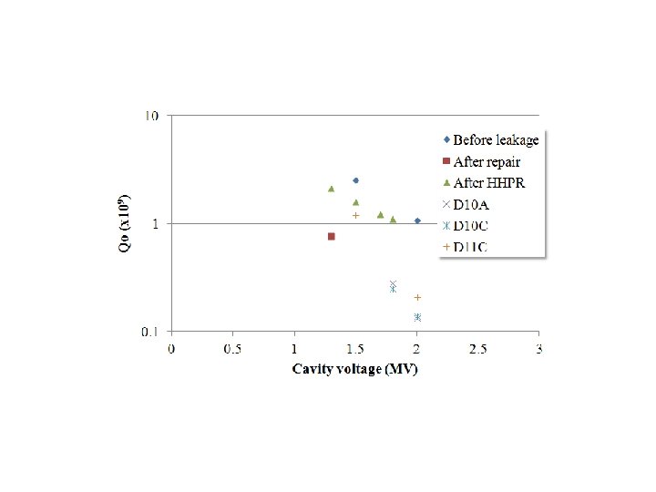
Vacuum leakage, repair and degradation • • Vacuum leakage happened at cooldown in May 2010 – Leakage at indium-sealed flange? Opened the cavity – Bolts of the flange were loose (60 kgf*cm) – Those bolts were retightened (150 kgf*cm) High power tested – No vacuum leakage – Q degradation with field emission • Voltage reached 1. 3 MV • Degraded Qo factor with FE • Limited by the radiation safety rule at test stand • Particle contamination Other degraded cavities – Degraded Q factors at ~2 MV • D 10 A, D 10 C, and D 11 C – Still acceptable for Super. KEKB operation – Performance recovery is desirable R&D for HHPR started in 2009. Leakage at indium sealed flange 10% Degraded Other degraded cavities
Horizontal HPR R&D using prototype test cavity Horizontal HPR was applied to our test cavity in the clean room Large BP Test cavity Small BP Water evacuation pipe (connected to aspirator) Horizontal insertion of HP water pipe High pressure rinsing Manually operated HHPR parameters (manual operation) Water Pressure 6 MPa Nozzle Stainless steal Φ 0. 54 mm x 6 Driving speed 0. 33 mm/sec (cell) 0. 66 mm/sec (BP) Rotation speed 120/sec Rinsing time 20 min
Cold test results after HHPR • • Before HHPR, EPII (10μm) Baked at 120 o. C Cold test after EPII 1 st HHPR – Rinsed cavity cell, iris and BP – Evacuated in vertical position – Residual water dropped on BP flange Cold test after 1 st HHPR w/o baking – Observed processing once – No degradation 2 nd HHPR – Evacuated in horizontal position – Residual water remained in cavity cell Cold test after 2 nd HHPR w/o baking – No degradation We confirmed that HHPR was applicable to our cavity 1 2 3 Vc(MV)
Improvements of HHPR for application to cryomodule HHPR in clean booth at assembly area • • Developed automatic nozzle driving system Water evacuation through the same BP Installed new ultrapure water system at assembly area After HHPR – Evacuate residual water in pickup port HHPR parameters (automatic operation) Water Pressure 7 MPa Nozzle Φ 0. 54 mm x 6 Driving speed 1 mm/sec Rotation speed 60/sec Rinsing time 10 -15 min Stainless steel nozzle Teflon tube to aspirate water in pickup port
Horizontal HPR in clean booth • • Before HHPR, EPII (10μm) once again baked at 120 o. C Cold test 3 rd HHPR – HHPR in clean booth at assembly area – New HHPR system – Rinsed cell and iris areas for 10 min. Cold test after 3 rd HHPR w/o baking – Fields reached to 8 MV/m (2 MV) – Fields degraded to 6 MV/m (1. 5 MV) with FE Inspected in clean room – Found a small pit <1 mm near LBP iris HHPR(4 th HHPR) – Rinsed cell and iris area for 15 min. • Wider SBP iris area Cold test after 4 th HHPR w/o baking – Qo recovered – w/o FE Effectiveness of HHPR was demonstrated Recovered Degraded 1 2 3 Vc(MV)
HHPR application to the degraded spare cavity Taking out the cavity from test stand Moving to the assembly area After the success of the HHPR to the test cavity, we applied HHPR to the performance degraded spare cavity. The cavity was moved to the assembly area in the KEKB tunnel. To the 4 th floor underground Landing
HHPR application to the spare module Taking out the inner conductor of the HPC End beam pipes and HOM dampers were dismounted Before we applied HHPR, HPC and HOM dampers were dismounted in a clean booth. Then the HHPR driver was set to the cavity. Setting the HHPR apparatus
HHPR application to the spare module Opening the dummy flange Water jets The degraded cavity was HHPR’ed with a new automatic drive and water evacuation system Automatic drive High pressure water pump Aspirator pumps Evacuation after HHPR
HPT results: Qo measurements HHPR’ed cavity was HP tested at 4. 4 K. The cavity voltage reached 2 MV and degraded Q factors recovered. The Qo value at 1. 5 MV was 1. 6 x 10⁹. This recovery is sufficient for the operation at Super. KEKB.
HHPR to another degraded cavity Recovered cavity installed into the HER ring HHPR setup for another degraded cavity HHPR’ed cavity in the test stand After the successful performance recovery, we tried HHPR to another degraded cavity. Performance recovered cavity was installed in the HER ring. On the other hand, degraded cavity was took out of the ring, then HHPR’ed in the assembly area. This cavity was installed in the test stand. The high power tests of this cavity will be conducted in February 2014. cavity
Summary • • We have developed HHPR using the test cavity – Horizontal insertion of the HP water nozzle – Water evacuation by the aspirator pump We applied HHPR to the degraded spare cavity module – RF performance recovered successfully – The recovery is sufficient for the operation at Super. KEKB – However, the recovery is not perfect • Further optimization (rinsing time/area)? • Re-contamination? Recovered cavity: Installed in the HER ring Another degraded cavity: HHP rinsed – to be HP tested in Feb. 2014
Horizontal HPR HHPR parameters (automatic operation) Water Pressure 7 MPa Nozzle Stainless steal Φ 0. 54 mm x 6 Driving speed 1 mm/sec Rotation speed 60/sec Rinsing time 15 min
HHPR application to our spare cavity module Dismounted end parts and HPC Moved the cavity to assembly area High pressure water jet in cavity cell Water jet nozzle and aspirator Set HHPR apparatus in clean booth Evacuate with residual water
Summary of leaked cavities and Q 0 degradations Date Operation phase Installed place Cavity ID Leaked at 1998/10/23 Cool-down D 11 B CA-B 03 He vessel, no influence on cavity vacuum pressure Repaired in April, 1999/05/20 Cool-down D 11 A CA-B 02 He vessel, no influence on cavity vacuum pressure Jan. 2001 Warm-up D 10 A CA-B 06 Indium seal of LBP, resealed in clean room Sep. 2001 Cool-down D 11 C CA-B 04 Indium seal of LBP, resealed in clean room 2004/01/09 Cool-down D 10 C CA-B 08 Indium seal of LBP, resealed in clean room 2004/12/25 In beam operation D 11 A CA-B 02 HOM damper flange, HOM damper exchanged Exchanged with CA-B 01 in June 2006 2005/07/02 Warm-up D 10 A CA-B 06 Indium seal of SBP or LBP, retorqued 2008/07/07 Summer shutdown D 11 A CA-B 01 Ion pump connector, retorqued 2010/05/01 Cool-down D 11 B CA-B 03 Indium seal of SBP or LBP, retorqued Exchanged with CA-B 02 in Nov. 2010 CA-B 02 Resealed with 0. 5 mm thick indium in Oct. 2006 Metal gaskets exchanged in Dec. 2006 Installed in KEKB in Nov. 2010 Q 0 degradation at Vc=2 MV 2004. 7. 8 HPC exchanged 2001. 1 Leak 2001. 7 installed 2005. 7 Leak 2005. 8. 31 installed
Input coupler conditioning before cool-down The input coupler has to be conditioned with fully reflected RF powers up to 300 k. W before cool-down. This conditioning took longer time than usual. RF trips occurred many times below 120 k. W by the vacuum pressure rise. Conditioning with minus biasing, especially at -600 V, reduced the vacuum pressure rise and increased input RF powers. Multipacting at the outer conductor would be the cause of the vacuum pressure rise. KEKB input coupler MP map Conditioning history +: Inner o: Inner-outer x: Outer