1415 Semester 4 Plant Utility System TKK2210 Instructor

- Slides: 31
14/15 Semester 4 Plant Utility System (TKK-2210) Instructor: Rama Oktavian Email: rama. oktavian 86@gmail. com Office Hr. : M-F 13 -15
Training Agenda: Waste Thermal Equipment/ Waste heat recovery Introduction Type of waste heat recovery Assessment of waste heat recovery 2 © UNEP 2006
Introduction Thermal Equipment/ Waste heat recovery What is Waste Heat? • “Dumped” heat that can still be reused • “Value” (quality) more important than quantity • Waste heat recovery saves fuel © UNEP 2006
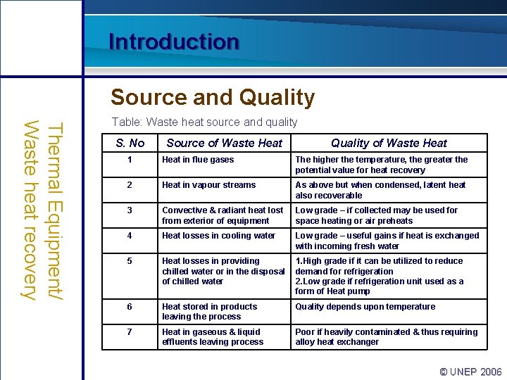
Introduction Source and Quality Thermal Equipment/ Waste heat recovery Table: Waste heat source and quality S. No Source of Waste Heat Quality of Waste Heat 1 Heat in flue gases The higher the temperature, the greater the potential value for heat recovery 2 Heat in vapour streams As above but when condensed, latent heat also recoverable 3 Convective & radiant heat lost from exterior of equipment Low grade – if collected may be used for space heating or air preheats 4 Heat losses in cooling water Low grade – useful gains if heat is exchanged with incoming fresh water 5 Heat losses in providing chilled water or in the disposal of chilled water 1. High grade if it can be utilized to reduce demand for refrigeration 2. Low grade if refrigeration unit used as a form of Heat pump 6 Heat stored in products leaving the process Quality depends upon temperature 7 Heat in gaseous & liquid effluents leaving process Poor if heavily contaminated & thus requiring alloy heat exchanger © UNEP 2006
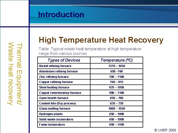
Introduction Thermal Equipment/ Waste heat recovery High Temperature Heat Recovery Table: Typical waste heat temperature at high temperature range from various sources Types of Devices Nickel refining furnace Aluminium refining furnace Temperature (0 C) 1370 – 1650 – 760 Zinc refining furnace 760 – 1100 Copper refining furnace 760 – 815 Steel heating furnace 925 – 1050 Copper reverberatory furnace 900 – 1100 Open hearth furnace 650 – 700 Cement kiln (Dry process) 620 – 730 Glass melting furnace 1000 – 1550 Hydrogen plants 650 – 1000 Solid waste incinerators 650 – 1000 Fume incinerators 650 – 1450 © UNEP 2006
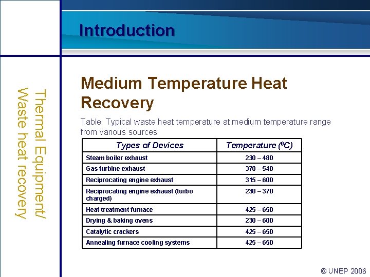
Introduction Thermal Equipment/ Waste heat recovery Medium Temperature Heat Recovery Table: Typical waste heat temperature at medium temperature range from various sources Types of Devices Temperature (0 C) Steam boiler exhaust 230 – 480 Gas turbine exhaust 370 – 540 Reciprocating engine exhaust 315 – 600 Reciprocating engine exhaust (turbo charged) 230 – 370 Heat treatment furnace 425 – 650 Drying & baking ovens 230 – 600 Catalytic crackers 425 – 650 Annealing furnace cooling systems 425 – 650 © UNEP 2006
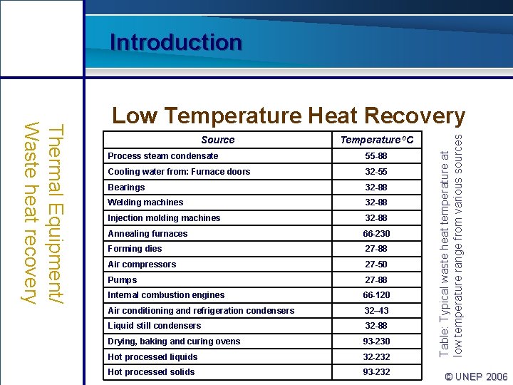
Introduction Source Temperature 0 C Process steam condensate 55 -88 Cooling water from: Furnace doors 32 -55 Bearings 32 -88 Welding machines 32 -88 Injection molding machines 32 -88 Annealing furnaces 66 -230 Forming dies 27 -88 Air compressors 27 -50 Pumps 27 -88 Internal combustion engines 66 -120 Air conditioning and refrigeration condensers 32– 43 Liquid still condensers 32 -88 Drying, baking and curing ovens 93 -230 Hot processed liquids 32 -232 Hot processed solids 93 -232 Table: Typical waste heat temperature at low temperature range from various sources Thermal Equipment/ Waste heat recovery Low Temperature Heat Recovery © UNEP 2006
Training Agenda: Waste Thermal Equipment/ Waste heat recovery Introduction Type of waste heat recovery Performance evaluation © UNEP 2006
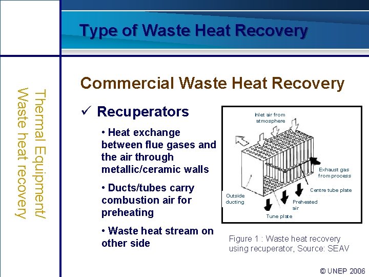
Type of Waste Heat Recovery Thermal Equipment/ Waste heat recovery Commercial Waste Heat Recovery ü Recuperators Inlet air from atmosphere • Heat exchange between flue gases and the air through metallic/ceramic walls • Ducts/tubes carry combustion air for preheating • Waste heat stream on other side Exhaust gas from process Centre tube plate Outside ducting Preheated air Tune plate Figure 1 : Waste heat recovery using recuperator, Source: SEAV © UNEP 2006
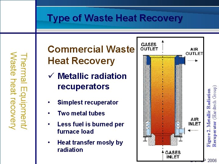
Type of Waste Heat Recovery ü Metallic radiation recuperators • Simplest recuperator • Two metal tubes • Less fuel is burned per furnace load • Heat transfer mosly by radiation Figure 2. Metallic Radiation Recuperator (Hardtech Group) Thermal Equipment/ Waste heat recovery Commercial Waste Heat Recovery 10 © UNEP 2006
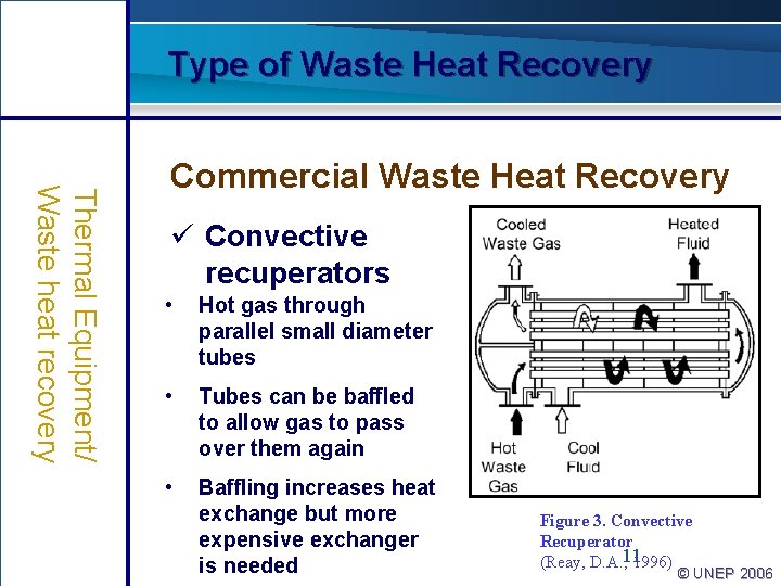
Type of Waste Heat Recovery Thermal Equipment/ Waste heat recovery Commercial Waste Heat Recovery ü Convective recuperators • Hot gas through parallel small diameter tubes • Tubes can be baffled to allow gas to pass over them again • Baffling increases heat exchange but more expensive exchanger is needed Figure 3. Convective Recuperator (Reay, D. A. , 11 1996) © UNEP 2006
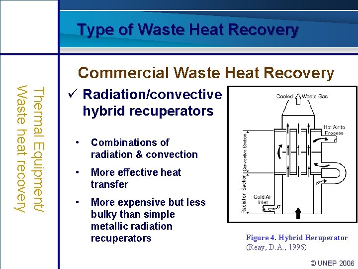
Type of Waste Heat Recovery Commercial Waste Heat Recovery Thermal Equipment/ Waste heat recovery ü Radiation/convective hybrid recuperators • Combinations of radiation & convection • More effective heat transfer • More expensive but less bulky than simple metallic radiation recuperators Figure 4. Hybrid Recuperator (Reay, D. A. , 1996) © UNEP 2006
Type of Waste Heat Recovery Thermal Equipment/ Waste heat recovery Commercial Waste Heat Recovery ü Ceramic recuperators • Less temperature limitations: • Operation on gas side up to 1550 ◦C • Operation on preheated air side to 815 ◦C • New designs • Last two years • Air preheat temperatures <700◦ C • Lower leakage rates © UNEP 2006
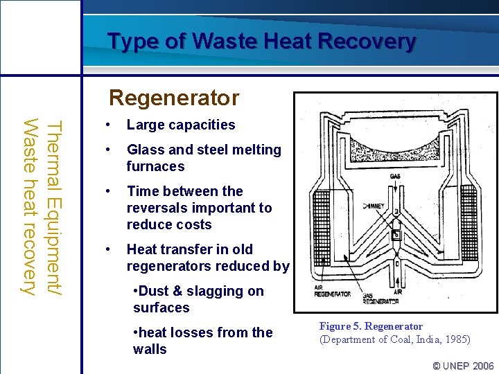
Type of Waste Heat Recovery Regenerator Thermal Equipment/ Waste heat recovery • Large capacities • Glass and steel melting furnaces • Time between the reversals important to reduce costs • Heat transfer in old regenerators reduced by • Dust & slagging on surfaces • heat losses from the walls Figure 5. Regenerator (Department of Coal, India, 1985) © UNEP 2006
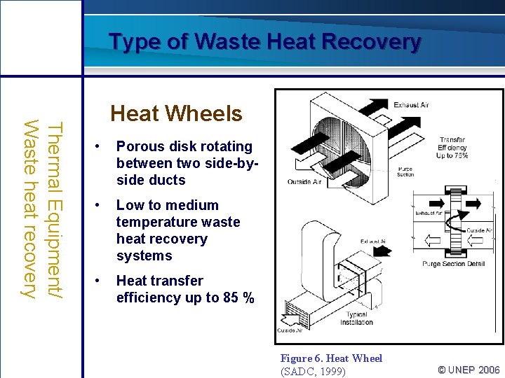
Type of Waste Heat Recovery Thermal Equipment/ Waste heat recovery Heat Wheels • Porous disk rotating between two side-byside ducts • Low to medium temperature waste heat recovery systems • Heat transfer efficiency up to 85 % Figure 6. Heat Wheel (SADC, 1999) © UNEP 2006
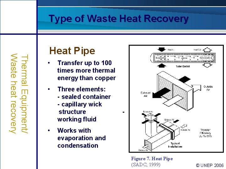
Type of Waste Heat Recovery Thermal Equipment/ Waste heat recovery Heat Pipe • Transfer up to 100 times more thermal energy than copper • Three elements: - sealed container - capillary wick structure working fluid • - Works with evaporation and condensation Figure 7. Heat Pipe (SADC, 1999) © UNEP 2006
Type of Waste Heat Recovery Thermal Equipment/ Waste heat recovery Heat Pipe ü Performance and advantage • Lightweight and compact • No need for mechanical maintenance, input power, cooling water and lubrication systems • Lowers the fan horsepower requirement and increases the overall thermal efficiency of the system • Can operate at 315 ◦C with 60% to 80% heat recovery © UNEP 2006
Type of Waste Heat Recovery Thermal Equipment/ Waste heat recovery Heat Pipe ü Typical application • Process to space heating - Transfers thermal energy from process exhaust for building heating • Process to process - Transfers recovered waste thermal energy from the process to the incoming process air • HVAC applications - Cooling and heating by recovering thermal energy © UNEP 2006
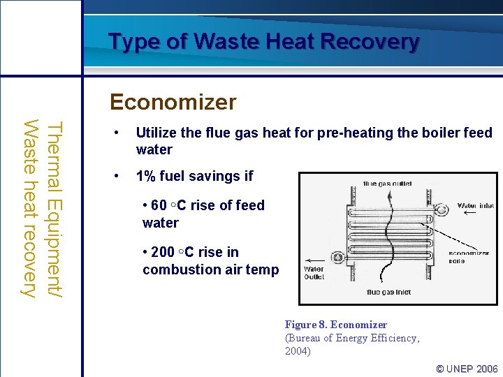
Type of Waste Heat Recovery Economizer Thermal Equipment/ Waste heat recovery • Utilize the flue gas heat for pre-heating the boiler feed water • 1% fuel savings if • 60 ◦C rise of feed water • 200 ◦C rise in combustion air temp Figure 8. Economizer (Bureau of Energy Efficiency, 2004) © UNEP 2006
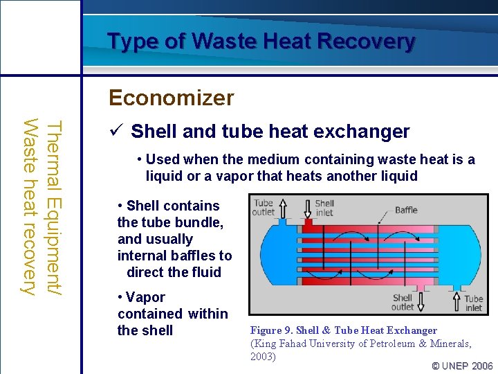
Type of Waste Heat Recovery Economizer Thermal Equipment/ Waste heat recovery ü Shell and tube heat exchanger • Used when the medium containing waste heat is a liquid or a vapor that heats another liquid • Shell contains the tube bundle, and usually internal baffles to direct the fluid • Vapor contained within the shell Figure 9. Shell & Tube Heat Exchanger (King Fahad University of Petroleum & Minerals, 2003) © UNEP 2006
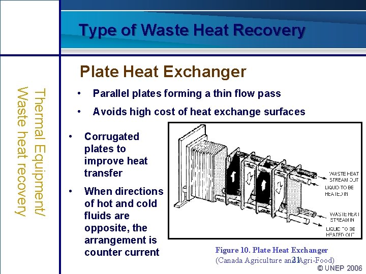
Type of Waste Heat Recovery Plate Heat Exchanger Thermal Equipment/ Waste heat recovery • Parallel plates forming a thin flow pass • Avoids high cost of heat exchange surfaces • Corrugated plates to improve heat transfer • When directions of hot and cold fluids are opposite, the arrangement is counter current Figure 10. Plate Heat Exchanger (Canada Agriculture and 21 Agri-Food) © UNEP 2006
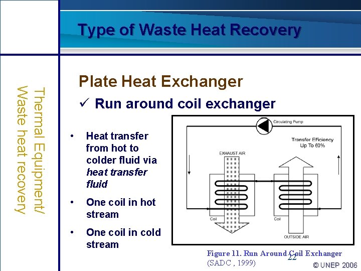
Type of Waste Heat Recovery Thermal Equipment/ Waste heat recovery Plate Heat Exchanger ü Run around coil exchanger • Heat transfer from hot to colder fluid via heat transfer fluid • One coil in hot stream • One coil in cold stream Figure 11. Run Around 22 Coil Exchanger (SADC , 1999) © UNEP 2006
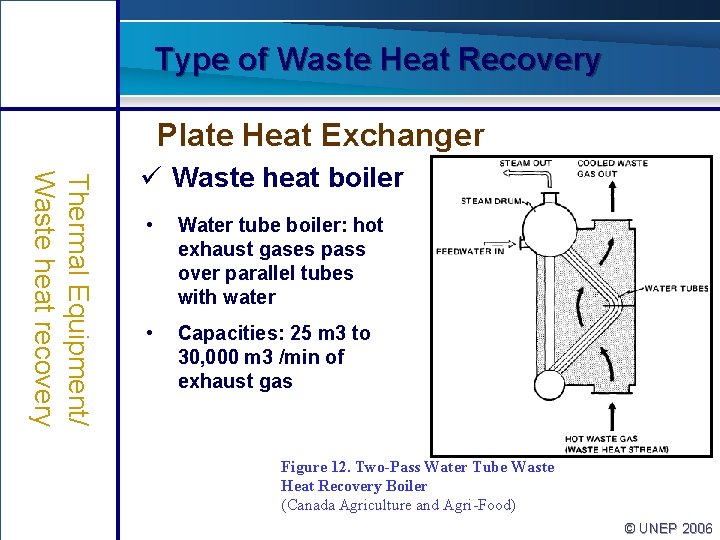
Type of Waste Heat Recovery Plate Heat Exchanger Thermal Equipment/ Waste heat recovery ü Waste heat boiler • Water tube boiler: hot exhaust gases pass over parallel tubes with water • Capacities: 25 m 3 to 30, 000 m 3 /min of exhaust gas Figure 12. Two-Pass Water Tube Waste Heat Recovery Boiler (Canada Agriculture and Agri-Food) © UNEP 2006
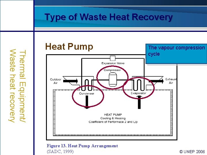
Type of Waste Heat Recovery Thermal Equipment/ Waste heat recovery Heat Pump Figure 13. Heat Pump Arrangement (SADC, 1999) The vapour compression cycle © UNEP 2006
Type of Waste Heat Recovery Heat Pump Thermal Equipment/ Waste heat recovery ü Developed as a space heating system ü Can upgrade heat >2 X the energy consumed by the device ü Most promising when heating and cooling capabilities are combined © UNEP 2006
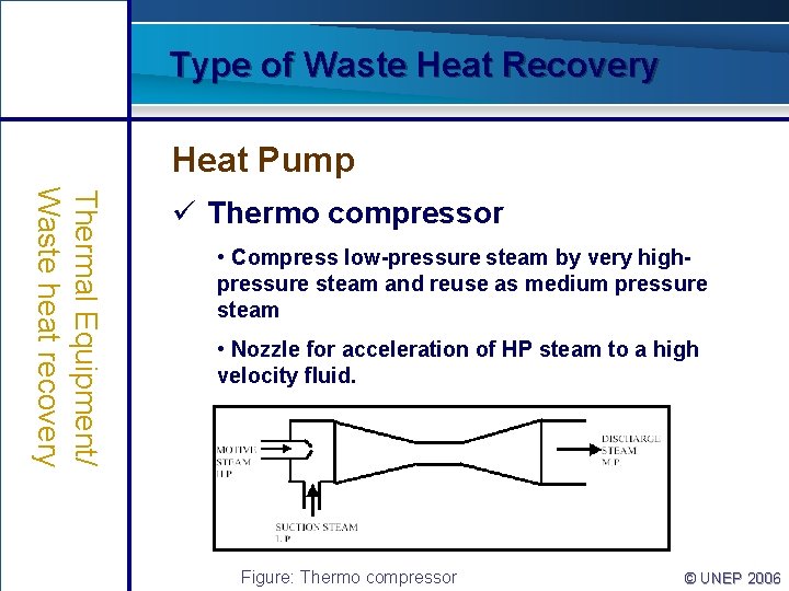
Type of Waste Heat Recovery Heat Pump Thermal Equipment/ Waste heat recovery ü Thermo compressor • Compress low-pressure steam by very highpressure steam and reuse as medium pressure steam • Nozzle for acceleration of HP steam to a high velocity fluid. Figure: Thermo compressor © UNEP 2006
Training Agenda: Waste Thermal Equipment/ Waste heat recovery Introduction Type of waste heat recovery Assessment of waste heat recovery © UNEP 2006
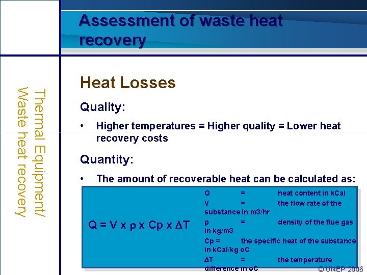
Assessment of waste heat recovery Thermal Equipment/ Waste heat recovery Heat Losses Quality: • Higher temperatures = Higher quality = Lower heat recovery costs Quantity: • The amount of recoverable heat can be calculated as: Q = V x x Cp x T Q = heat content in k. Cal V = the flow rate of the substance in m 3/hr = density of the flue gas in kg/m 3 Cp = the specific heat of the substance in k. Cal/kg o. C T = the temperature 28 difference in o. C © UNEP 2006
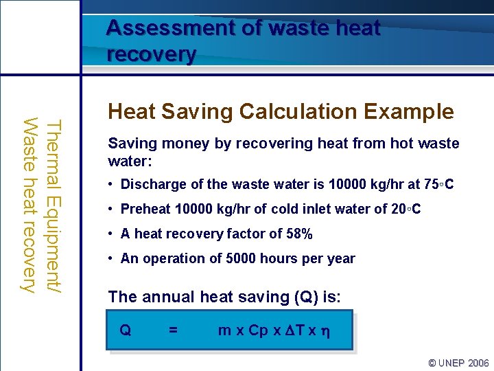
Assessment of waste heat recovery Thermal Equipment/ Waste heat recovery Heat Saving Calculation Example Saving money by recovering heat from hot waste water: • Discharge of the waste water is 10000 kg/hr at 75◦C • Preheat 10000 kg/hr of cold inlet water of 20◦C • A heat recovery factor of 58% • An operation of 5000 hours per year The annual heat saving (Q) is: Q = m x Cp x T x © UNEP 2006
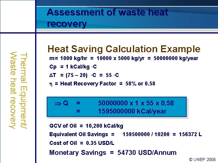
Assessment of waste heat recovery Thermal Equipment/ Waste heat recovery Heat Saving Calculation Example m = 1000 kg/hr = 10000 x 5000 kg/yr = 50000000 kg/year Cp = 1 k. Cal/kg ◦C T = (75 – 20) ◦C = 55 ◦C = Heat Recovery Factor = 58% or 0. 58 Q = = 50000000 x 1 x 55 x 0. 58 1595000000 k. Cal/year GCV of Oil = 10, 200 k. Cal/kg Equivalent Oil Savings = 159500000 / 10200 = 156372 L Cost of Oil = 0. 35 USD/L Monetary Savings = 54730 USD/Annum © UNEP 2006