1 3 1 Pressure relief valve The pressure


- Slides: 15

1 3. 1 Pressure relief valve The pressure relief valves are used to protect the hydraulic components from excessive pressure. This is one of the most important components of a hydraulic system and is essentially required for safe operation of the system. Its primary function is to limit the system pressure within a specified range. At no time should the relief valve be used to pass excess pressure fluid to tank. When excess pump flow goes to tank, it generates heat. The relief valve in a welldesigned hydraulic circuit never relieves oil to tank, unless there is a circuit or control malfunction. Think of a relief valve in a hydraulic system as a fuse or circuit breaker in an electric circuit. An electric circuit never blows a fuse unless it overloads. When an electric circuit overloads, it is inoperable until reset. Usually the person responsible for resetting the fuse looks for the reason it blew and fixes the problem before restarting the machine. Many hydraulic circuits allow the relief valve to dump some or all pump flow to tank all or part of the time. The extra power to produce that unused flow is expensive. Also, heat generation from excess flow requires larger heat exchangers that are expensive to buy and operate. 3. 1. 1 Types of pressure relief valve There are many types of pressure relief valve, the most commonly used are: 1. Direct pressure-relief valve 2. Pressure-reducing valve. 3. Unloading valve 4. Counterbalance valve. 5. Pressure-sequence valve. 6. Brake valve. The details of each type will be described in next sections 1. Direct pressure-relief valve (a) (b) Figure 4. 1: direct pressure relief valve (a) symbol (b) schematic

2 Schematic of direct pressure relief valve is shown in figure 4. 1. It is normally a closed valve whose function is to limit the pressure to a specified maximum value by diverting pump flow back to the tank. This type of valves has two ports; one of which is connected to the pump and another is connected to the tank. It consists of a spring chamber where poppet is placed with a spring force. Generally, the spring is adjustable to set the maximum pressure limit of the system. The poppet is held in position by combined effect of spring force and dead weight of spool. As the pressure exceeds this combined force, the poppet raises, and excess fluid bypassed to the reservoir (tank). The poppet again reseats as the pressure drops below the pre-set value. A drain is also provided in the control chamber. It sends the fluid collected due to small leakage to the tank and thereby prevents the failure of the valve. The main advantage of direct-acting relief valves over pilot-operated relief valves is that they respond very rapidly to pressure build-up. Because there is only one moving part in a direct-acting relief valve, it can open rapidly, thus minimizing pressure spikes. Example 3. 1 A pressure-relief valve contains a poppet with an area of 4. 2 cm 2 on which the system pressure acts. During assembly, a spring with a spring constant of 3300 N/cm is installed in the valve to hold the poppet against its seat. The adjustment mechanism is then set so that the spring is initially compressed to 0. 5 cm from its free-length condition. In order to pass full pump flow through the valve at the pressure-relief valve pressure setting, the poppet must move 0. 30 cm from its fully closed position. (a) Determine the cracking pressure. (b) Determine the full pump flow pressure (pressure-relief valve pressure setting). (c) What should be the initial compression of the spring in pressure-relief valve if the full pump flow is to be 40% greater than the cracking pressure

3 Example 3. 2 A pressure-relief valve contains a poppet with a 3. 87 cm 2 area on which the system pressure acts. The poppet must move 0. 381 cm from its fully closed position in order to pass pump flow at the pressure-relief valve setting (full pump flow pressure). The pressure required to overcome the external load is 68. 95 bar. Assume that the pressure-relief valve setting is 50% higher than the pressure required to overcome the external load. If the valve-cracking pressure is 10% higher than the pressure required to overcome the external load, find the following: (a) The required spring constant of the compression in the valve. (b) The required initial compression of the spring from its free length condition as set by the spring adjustment mechanism of the pressure-relief valve.

4 2. Pressure Reducing Valve This valve is actuated by the downstream pressure and tends to close as the pressure reaches the valve setting as in fig. 4. 2. When the downstream pressure is below the valve setting, fluid will flow freely from the inlet to the outlet. Observe that there is an internal passage from the outlet, which transmits the outlet pressure to the spool end opposite the spring. When the downstream pressure increases beyond the value of the spring setting, the spool moves upward to partially block the outlet port as shown in Figure It can be seen from the figure 4. 3 that if the spring force is more, the valve opens wider and if the controlled pressure has greater force, the valves moves towards the spring and throttles the flow. Figure 4. 2: symbol of pressure reducing valve

5 Figure 4. 3: schematic of pressure reducing valve (left) fully opened (right) fully closed A reducing valve is normally open. It reads the downstream pressure. It has an external drain. This is represented by a line connected from the valve drain port to the tank. The symbol shows that the spring cavity has a drain to the tank. Application of pressure-reducing valve Let us consider a hydraulic circuit where one cylinder is required to apply a lesser force than the other as shown in Figure 4. 4. Here cylinder B is required to apply a lesser force than cylinder A. This is accomplished as follows. Figure 4. 4: Application of a pressure-reducing valve

6 A pressure-reducing valve is placed just before cylinder B in the hydraulic circuit as shown. This arrangement allows flow to the cylinder, until the set pressure value on the valve is reached. At this point where the set pressure is reached, the valve shuts off, thereby preventing any further build-up of pressure. The fluid is bled to the tank through the drain valve passage resulting in the easing-off of the pressure, as a result of which the valve opens again. Finally, a reduced modulated pressure equal to the valve results. 3. Unloading Valve Unloading valves are remotely piloted, normally closed pressure control valves, used to direct flow to the tank when pressure at a particular location in a hydraulic circuit reaches a predetermined value. Construction of the unloading valve is shown in Figure 4. 5. This valve consists of a control chamber with an adjustable spring which pushes the spool down. The valve has two ports: one is connected to the tank and another is connected to the pump. The valve is operated by movement of the spool. Normally, the valve is closed, and the tank port is also closed. These valves are used to permit a pump to operate at the minimum load. It works on the same principle as direct control valve that the pump delivery is diverted to the tank when sufficient pilot pressure is applied to move the spool. The pilot pressure maintains a static pressure to hold the valve opened. The pilot pressure holds the valve until the pump delivery is needed in the system. As the pressure is needed in the hydraulic circuit; the pilot pressure is relaxed, and the spool moves down due to the self-weight and the spring force. Now, the flow is diverted to the hydraulic circuit. The drain is provided to remove the leaked oil collected in the control chamber to prevent the valve failure. The unloading valve reduces the heat build-up due to fluid discharge at a pre-set pressure value. (a) (b) Figure 4. 5: (a) schematic of unloading valve (b) symbol of unloading valve

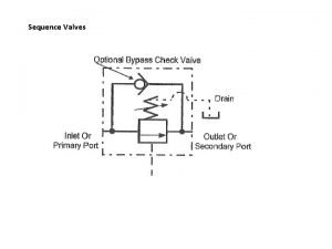
7 Figure 4. 6: Application of unloading valve 4. Sequence valve In circuits with more than one actuator, it’s often necessary to drive the actuators, such as cylinders, in a definite order or sequence. This can be done with limit switches, timers, or other electrical control devices. Sequence valves are normally closed 2 -way valves that regulate the sequence in which various functions in a circuit occur, Figure 4. 7 and 4. 8. They resemble direct-acting relief valves except that their spring chambers are generally drained externally to tank, instead of internally to an outlet port. Normally, a sequence valve routes pressurized fluid to a second function only after an earlier function has been completed. When normally closed, a sequence valve allows fluid to flow freely to the primary circuit to perform its first function until the valve’s pressure setting is reached. When the priority function is satisfied, pressure in the primary circuit rises and is sensed in pressure-sensing passage A. This pressurizes fluid acting on the spool and overcomes the force exerted by the spring. The spring is compressed, the spool shifts, and fluid flows to the secondary circuit.

8 Figure 4. 7: schematic of sequence valve (left) open to primary circuit (right) open to secondary circuit Figure 4. 8: symbol of sequence valve Application of a Sequence Valve In this circuit, two cylinders are connected in parallel. Without the sequence valve, these cylinders would extend together as they are both unloaded as in fig. 4. 9. In order for this circuit to function properly, the clamp cylinder must extend completely before the bending cylinder begins to extend. The sequence valve accomplishes this by not allowing flow into the bending cylinder branch of circuit until the clamp cylinder has reached the end of its stroke. When the clamp cylinder extends completely, the pressure rises and opens the sequence valve, thus allowing the bending cylinder to extend as in figures 4. 10 and 4. 11. The sequence valve must be set high enough so that it opens only after the complete extension of the clamp cylinder. During the retraction of cylinders, the check valve allows the sequence valve to be bypassed. The sequence valve has no effect on the circuit in this situation. Both cylinders retract together

9 because both are unloaded and split the pump flow. In order to fix the workspace after bending process, another sequence valve can be used as in figures 4. 12 and 4. 13. Figure 4. 9: clamping and bending cylinder extended together (without sequence valve) (a)

10 (b) Figure 4. 10: clamping cylinder extended first and then bending cylinder (with one sequence valve) Figure 4. 11: clamping cylinder and bending cylinder retract together in the same time (with one sequence valve)

11 (a) (b) Figure 4. 12: clamping cylinder extends first and then bending cylinder (with two sequence valve)

12 Figure 4. 13: bending cylinder retracts first and then bending cylinder (with two sequence valve) 5. Counterbalance Valve The schematic of counterbalance valve is shown in Figure 4. 14. It is used to maintain the back pressure and to prevent a load from failing. The counterbalance valves can be used as breaking valves for decelerating heavy loads. These valves are used in vertical presses, lift trucks, loaders and other machine tools where position or hold suspended loads are important. Counterbalance valves work on the principle that the fluid is trapped under pressure until pilot pressure overcomes the pre-set value of spring force. Fluid is then allowed to escape, letting the load to descend under control. This valve is normally closed until it is acted upon by a remote pilot pressure source. Therefore, a lower spring force is sufficient. It leads to the valve

13 operation at the lower pilot pressure and hence the power consumption reduces, pump life increases and the fluid temperature decreases. Figure 4. 14: Counterbalance valve schematic and symbol Application of a Counterbalance Valve Counterbalance valves are commonly used to counterbalance a weight or external force or counteract a weight such as a platen or a press and keep it from freefalling. Figure 4. 15 illustrates the use of a counterbalance or back-pressure valve to keep a vertically mounted cylinder in the upward position while the pump idles, that is, when the DCV is in its centre position. During the downward movement of the cylinder, the counterbalance valve is set to open at slightly above the pressure required to hold the piston up (a check valve does not permit flow in this direction). The control signal for the counterbalance valve can be obtained from the blank end or rod end of the cylinder.

14 Figure 4. 15: Counterbalance valve application When a counterbalance valve is used in large vertical presses, it may be important to analyze the source of pilot operating pressure. Figure 4. 16 shows a comparison between direct pilot and remote pilot operation. When there is no pressure applied to the full piston side of a cylinder (figure 4. 16 a), the valve will maintain oil in the rod side. The two pilot lines shown act on different areas inside the valve. The ratio of these areas is usually 3: 1 or 4: 1. For explanation we will use the 3: 1 ratio. The line connected between the valve and cylinder's rod side acts on a small piston area (1 square inch) inside the valve. To overcome a spring tension of 1, 800 lbs, the pressure would have to build to 1800 PSI. Since the load in the example is exerting a force of only 1500 PSI, the valve will remain closed. When necessary to lower the load, the full piston side of the cylinder is pressurized. The "remote" pilot line will then be pressurized to open the valve. The remote pilot line acts on three times the area (3 square inches) than the internal pilot line acts upon. Actually, 1, 500 lbs of force is already being exerted by the load on the spring. Therefore, the remote pilot pressure only has to develop 300 lbs. of additional force. pressure only has to build to 100 PSI on the 3 -square inch surface area to equal 300 lbs. of force. (figure 4. 16 b).

15 (a) (b) Figure 4. 16: Counterbalance valve application
 Check valve symbol
 Pilot operated pressure relief valve symbol
 Hydraulic signs and symbols
 Servo valve function
 Colt international ltd
 Goole valve
 Flow restrictor valve symbol
 Belimo picv valves
 Counterbalance valve symbol
 Pressure reliefe valve
 Pneumatic
 Mật thư anh em như thể tay chân
 Chụp phim tư thế worms-breton
 Tư thế ngồi viết
 ưu thế lai là gì
 Thẻ vin
