True stress and True strain From fig 4


 True stress-strain curve")


- Slides: 15
True stress and True strain From fig 4 , the decline in the stress necessary to continue deformation past the maximum, point M, seems to indicate that the metal is becoming weaker. However, the cross-sectional area is decreasing rapidly within the neck region, where deformation is occurring. The stress, as computed from Equation 1, is on the basis of the original cross sectional area before any deformation, and does not take into account this reduction in area at the neck. Sometimes it is more meaningful to use a true stress–true strain scheme. True stress is defined as the load F divided by the instantaneous cross-sectional area over which deformation is occurring (i. e. , the neck, past the tensile point)
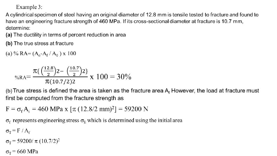
Engineering stress E = F / Ao where Ao is original area True stress ( T) = F/ Ai , where Ai is the area where the fracture occurring at the necking region
Figure (10) True stress-strain curve
Ductile and Brittle materials fracture Fracture: separation of a body into pieces due to stress, at temperatures below the melting point. Steps in fracture: 1 - crack formation 2 - crack propagation In ductile fracture, the crack grows at a slow pace and is accompanied with a great deal of plastic deformation due to the motion of dislocation. In this, the crack does not expand except when high levels of stress are present. Under the view of a microscope, the surfaces of materials with ductile fracture appear irregular and rough, and exhibit some dimpling Figure (11) Steps of fracture for ductile materials Figure (12) Dislocations motion in ductile materials
Brittle Fracture Very little or no plastic deformation, Crack propagation is very fast , Crack propagates nearly perpendicular to the direction of the applied stress, Crack often propagates by cleavage - breaking of atomic bonds along specific crystallographic planes (cleavage planes). Figure (12) difference in cracks for ductile and brittle materials Figure (13) Crack propagation in Brittle materials
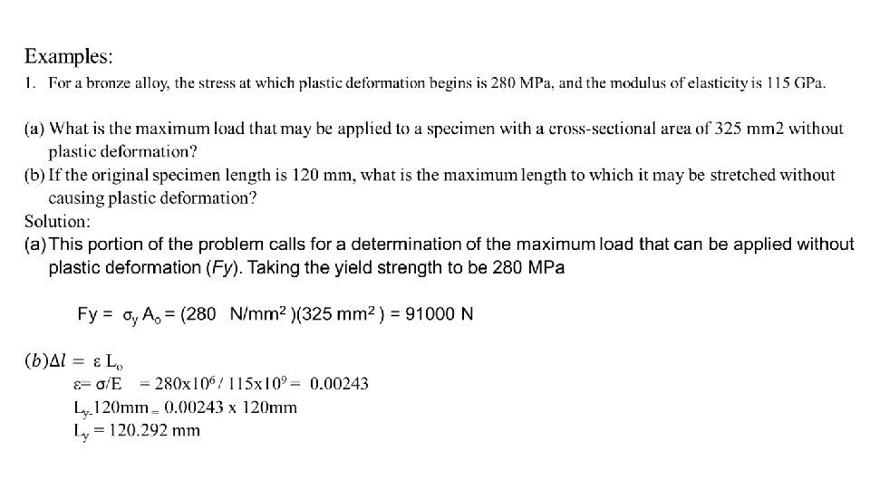
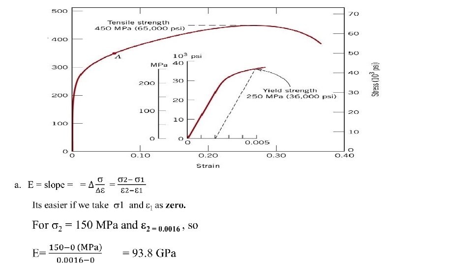
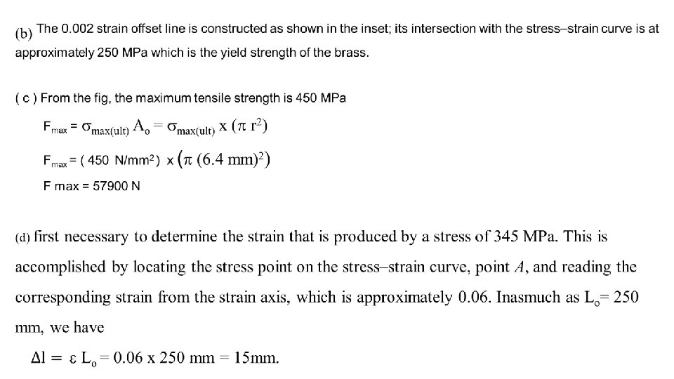
Example #2: From the tensile stress–strain behavior for the brass specimen shown in Figure below determine the following: (a) The modulus of elasticity (b) The yield strength at a strain offset of 0. 002 (c) The maximum load that can be sustained by a cylindrical specimen having an original diameter of 12. 8 mm (d) The change in length of a specimen originally 250 mm long that is subjected to a tensile stress of 345 MPa
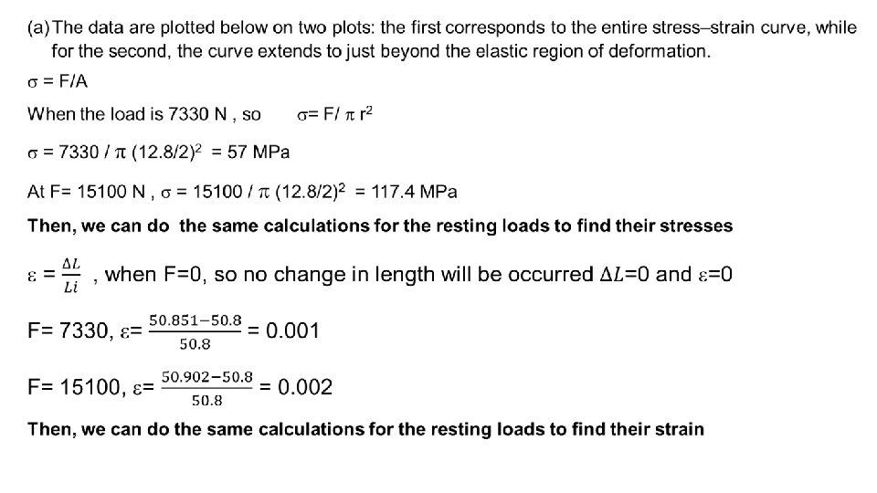
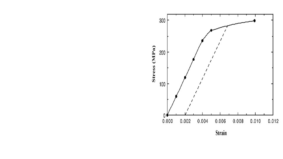
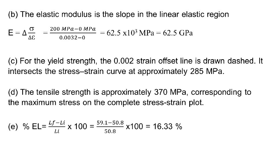
Example 4: A cylindrical specimen of aluminum having a diameter of 12. 8 mm and a gauge length of 50. 800 mm is pulled in tension. Use the load–elongation characteristics shown in the following table to complete parts (a) through (e). Load N 0 7, 330 15, 100 23, 100 30, 400 34, 400 38, 400 41, 300 44, 800 46, 200 47, 300 47, 500 46, 100 44, 800 42, 600 36, 400 Length mm 50. 800 50. 851 50. 902 50. 952 51. 003 51. 054 51. 308 51. 816 52. 832 53. 848 54. 864 55. 880 56. 896 57. 658 58. 420 59. 1 (a) Plot the data as engineering stress versus engineering strain. (b) Compute the modulus of elasticity. (c) Determine the yield strength at a strain offset of 0. 002. (d) Determine the tensile strength of this alloy. (e) What is the approximate ductility, in percent elongation?
Example 5 : For some metal alloy, a true stress of 345 MPa produces a plastic true strain of 0. 02. How much will a specimen of this material elongate when a true stress of 415 MPa is applied if the original length is 500 mm? Assume a value of 0. 22 for the strain-hardening exponent, n. σT = K (εT) n Next we must solve for the true strain produce when a true stress of 415 MPa is applied