Traveling Wave Transient Overvoltages 1 Introduction Transient Phenomenon


- Slides: 26

Traveling Wave Transient Overvoltages

1. Introduction • Transient Phenomenon : – Aperiodic function of time – Short duration • Example : Voltage & Current Surge : (The current surge are made up of charging or discharging capacitive currents that introduced by the change in voltages across the shunt capacitances of the transmission system) – Lightning Surge – Switching Surge

Impulse Voltage Waveform

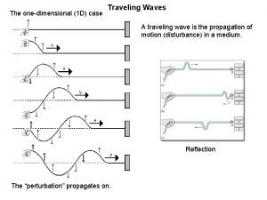
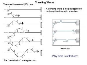
2. Traveling Wave • • Disturbance represented by closing or opening the switch S. If Switch S closed, the line suddenly connected to the source. The whole line is not energized instantaneously. Processed : – When Switch S closed – The first capacitor becomes charged immediately – Because of the first series inductor (acts as open circuit), the second capacitor is delayed • This gradual buildup of voltage over the line conductor can be regarded as a voltage wave is traveling from one end to the other end

Voltage & Current Function • • • vf=v 1(x- t) vb=v 2(x+ t) = 1/ (LC) v(x, t)=vf + vb vf=Zcif vb=Zcib • • • Zc=(L/C)½ If=vf/Zc Ib=vb/Zc I(x, t)=If + Ib I(x, t)=(C/L) ½ [v 1(x- t) -v 2(x+ t)]

2. 1 Velocity of Surge Propagation • In the air = 300 000 km/s • = 1/ (LC) m/s • Inductance single conductor Overhead Line (assuming zero ground resistivity) : L=2 x 10 -7 ln (2 h/r) H/m C=1/[18 x 109 ln(2 h/r)] F/m • • In the cable : = 1/ (LC) = 3 x 10⁸ K K=dielectric constant (2. 5 to 4. 0) m/s

2. 2 Surge Power Input & Energy Storage • • P=vi Watt Ws= ½ Cv 2 ; Wm= ½ Li 2 W=Ws+Wm = 2 Ws = 2 Wm = Cv 2 = Li 2 P=W = Li 2 / (LC) = i 2 Zc = v 2 / Zc

2. 3 Superposition of Forward and Backward-Traveling Wave

3. Effects of Line Termination • Assuming vf, if, vb and ib are the instantaneous voltage and current. Hence the instantaneous voltage and current at the point discontinuity are : • • v(x, t)=vf + vb and I=vf/Zc - vb/Zc and v + i. Zc= 2 vf so vf = ½ (v+i. Zc) and I(x, t)=If + Ib i. Zc=vf – vb v=2 vf=i. Zc vb = ½ (v+i. Zc) or vb= vf-i. Zc

3. 1 Line Termination in Resistance

3. 2 Line Termination in Impedance (Z)

• Line is terminated with its characteristic impedance : – Z=Zc – =0, no reflection (infinitely long) • Z>Zc – vb is positive – Ib is negative – Reflected surges increased voltage and reduced current • Z<Zc – vb is negative – Ib is positive – Reflected surges reduced voltage and increased current • Zs and ZR are defined as the sending-end and receiving end. •


3. 3 Open-Circuit Line Termination • • Boundary condition for current i=0 Therefore if=-ib Vb=Zcib=Zif=vf Thus total voltage at the receiving end v=vf+vb=2 vf • Voltage at the open end is twice the forward voltage wave

3. 4 Short Circuit Line Termination • • Boundary condition for current v=0 Therefore vf=-vb If=vf/Zc=-(vb/Zc)=ib Thus total voltage at the receiving end v=if+ib=2 if • Current at the open end is twice the forward current wave


3. 5 Termination Through Capacitor


3. 6 Termination Through Inductor

4. Junction of Two Line


5. Junction of Several Line Example:


6. Bewley Lattice Diagram

 Switching overvoltages in ehv and uhv systems
 Traveling wave
 Traveling wave
 Light is electromagnetic wave true or false
 Short wave vs long wave radiation
 Difference between full wave and half wave rectifier
 Transverse and longitudnal waves
 20 v
20 v Transformer bridge rectifier circuit
 Determining the arrival times between p-wave and s-wave
 Rectified sine wave fourier series
 Nature of sound wave
 The nature of waves chapter 10 section 1
 Half wave symmetry
 Mechanical waves and electromagnetic waves
 What are the mechanical waves
 Velocity frequency wavelength triangle
 Traveling is very popular nowadays
 Traveling salesman problem erklärung
 A 65 kg astronaut weighs 638
 Power of lens
 Step 1
 Gerunde
 Bitonic euclidean traveling salesman problem
 The old lamp made in china is five dollars
 What are lines sections elevations and guidelines
 Which universal force can repel as well as attract?

