Submitted by Project overview Block diagram Power supply

Submitted by:

� Project overview � Block diagram � Power supply � Microcontroller � MAX 232 & DB 9 Connector � Relay driver � Software requirements � Schematic & Working of the project � Advantages � Applications � Future scope � Conclusion

� This project constitutes external load for home applications controlled with the help of PC. � An Embedded project is a combination of hardware and software, designed to perform a specific task. � In embedded technology, the embedded programming is burnt into the microcontroller. � PC is connected to microcontroller through a level shifter IC, ULN 2003 (Driver) is used to drive the relays, and from relays we can connect external devices. � MAX-232 is used as voltage level shifter because PC voltage levels and microcontroller voltage levels are different. DB 9 (RS-232) connector is used to connect to PC com port. � It can also manage a new economical solution of theater light control systems.
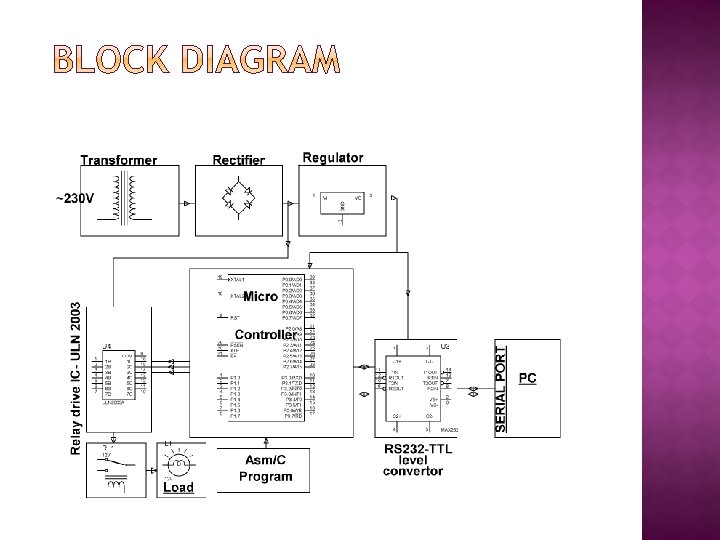

Step down transformer Bridge rectifier Filter Regulator

� The 230 V AC supply is first stepped down to 12 V AC using a step down transformer. � This is then converted to DC using bridge rectifier. � The AC ripples is filtered out by using a capacitor and given to the input pin of voltage regulator 7805. � At output pin of this regulator we get a constant 5 V DC which is used for MC and other ICs in this project.

� It is a smaller computer � Has on-chip RAM, ROM, I/O ports. . . CPU I/O Port RAM ROM Serial Timer COM Port A single chip Microcontroller

External interrupts Interrup t Control On-chip ROM for program code Timer/Counter On-chip RAM Timer 1 Timer 0 CPU OSC Bus Control 4 I/O Ports P 0 P 1 P 2 P 3 Address/Data Serial Port Tx. D Rx. D Counter Inputs
 Flash Memory � 4. 0 V")
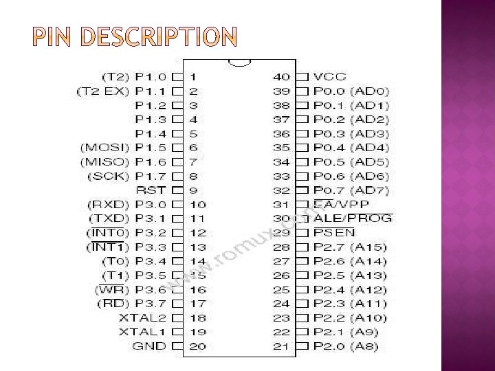
� 8 K Bytes of In-System Programmable (ISP) Flash Memory � 4. 0 V to 5. 5 V Operating Range � Fully Static Operation: 0 Hz to 33 MHz � 256 x 8 -bit Internal RAM � 32 Programmable I/O Lines � Three 16 -bit Timer/Counters � Eight Interrupt Sources � Full Duplex UART Serial Channel

+5 V + 10 u. F 31 30 p. F 8. 2 K 30 p. F 11. 0592 MHz 19 18 EA/VPP X 1 X 2 9 RST

� The MAX 232 is an integrated circuit that converts signals from an RS-232 serial port to signals suitable for use in TTL compatible digital logic circuits. � The MAX 232 is a dual driver/receiver and typically converts the RX, TX, CTS and RTS signals. � When a MAX 232 IC receives a TTL level to convert, it changes a TTL Logic 0 to between +3 and +15 V, and changes TTL Logic 1 to between -3 to -15 V, and vice versa for converting from RS 232 to TTL.
 connector is an analog 9 -pin plug of")
� The DB 9 (originally DE-9) connector is an analog 9 -pin plug of the D-Sub miniature connector family.

�A relay is an electrically operated switch. � Current flowing through the coil of the relay creates a magnetic field which attracts a lever and changes the switch contacts. � The coil current can be on or off so relays have two switch positions and have double throw (changeover) switch contacts as shown in the diagram.

� Relays allow one circuit to switch a second circuit which can be completely separate from the first. � For example a low voltage battery circuit can use a relay to switch a 230 V AC mains circuit. � There is no electrical connection inside the relay between the two circuits, the link is magnetic and mechanical. � To drive relay through MC ULN 2003 relay driver IC is used

� ULN is Relay driver application � The ULN 2003 is a monolithic high voltage and high current Darlington transistor arrays. � It consists of seven NPN Darlington pairs that features high-voltage outputs with commoncathode clamp diode for switching inductive loads. � The collector-current rating of a single Darlington pair is 500 m. A. � The Darlington pairs may be paralleled for higher current capability.

� The ULN functions as an inverter. � If the logic at input 1 B is high then the output at its corresponding pin 1 C will be low.

� Keil an ARM Company makes C compilers, macro assemblers, real-time kernels, debuggers, simulators, integrated environments, evaluation boards, and emulators for ARM 7/ARM 9/Cortex-M 3, XC 16 x/ST 10, 251, and 8051 MCU families. � Compilers are programs used to convert a High Level Language to object code. Desktop compilers produce an output object code for the underlying microprocessor, but not for other microprocessors.

� i. e the programs written in one of the HLL like ‘C’ will compile the code to run on the system for a particular processor like x 86 (underlying microprocessor in the computer). � For example compilers for Dos platform is different from the Compilers for Unix platform So if one wants to define a compiler then compiler is a program that translates source code into object code.

� The project uses a PC to control the loads. � The commands are received by the micro controller through level shifted IC Max 232. � When the program is executed, it drives relay from the microcontroller through relay driver IC ULN 2003. � Load’s are switched ON and switched OFF based on the corresponding command sent from the keyboard through hyperterminal. � As per the program, the loads will be turned ON and OFF through the relays.

- Slides: 21