SIMPLIFIED WET ASH ARRESTING SYSTEM OPERATION AT DARYA


 A. Application and Performance: An electrostatic precipitator is a device")


 m 3 of wet flue gas/Kg Bagasse(fuel)")
 set the standard of")

- Slides: 26
SIMPLIFIED WET ASH ARRESTING SYSTEM OPERATION AT DARYA KHAN SUGAR MILLS By Engr. Abdul Aziz Tahir, X-Group Technical Director To be presented at, 53 rd Annual Convention of Pakistan Society of Sugar Technologists
Simplified Wet Ash Arresting System Operation at Darya khan Sugar Mills Engr. Abdul Aziz Tahir* 1. Abstract: There are no. of techniques to combat the fly ash carryover with Boiler flue gas in Cane Sugar Industry. These are mainly dry Ash Collecting Cyclones, Wet Scrubbing, Electrostatic Precipitation and Wet Ash Arresting with Water Showing & Recycling. The Wet Ash Arresting System (WAAS) with water showering and recycling in a closed circuit, is the best ash arresting system for the Sugar Industry Boiler. The performance of the WAAS is improved if ash collection load is decreased with in-line installation of dry ash collecting cyclones system at primary stage. At Darya khan Sugar Mills wet ash arresting system was installed with the erection of the boiler but it was not operative since long due to certain reasons. In off season 2018, major low cost modifications were made at site and system operated with success in season 2018 -19. Full detail of modification, design, erection and operation of the system is discussed in the underlined paper *X-Group Technical Director, Darya Khan Sugar Mills, Darya Khan, Distt. Bhakkar
2. Introduction: Darya khan with 1 st name as Adam Sugar Mills started its operation in 1976 -77. In second Management group “ Fecto Group” plant capacity was increased with addition of second mill tandem and Descon designed 80 tons, bi-drum, water tube, suspension grate furnace type Boiler. The boiler included fly ash arresting cyclones and wet ash arresting system. The ash arresting system included; concrete duct in between Induced Draft Fan and Boiler Chimney with fixed S. S spray mist nozzles installed in the top roof of concrete duct and ash collecting pit with spray water pump. The installed system for ash arresting was not in operation since long due to certain reasons. In off season 2018 major low cost modifications were made at site and system operated with success in season 2018 -19. The detail of modification, erection and operation work is discussed in detail in Material and Method section of the paper. Here is a review of the some industrial applicable ash arresting techniques:
A. Fly Ash Collecting Cyclones a. Application and Performance : The cyclone is widely used type of particulate collection device in which dust laden gas enters tangentially into a cylinder or conical chamber and leave through a central opening. The resulting vortex motion or spiraling gas flow pattern creates a strong centrifugal force filed in which dust particles, by virtue of their inertia, separate from the carrier gas stream. The ash particles migrate along the cyclone walls by gas flow and gravity forces and ultimately fall into storage receiver in the bottom side of the cyclone. The particulates are composed of fly ash and un-burnt constitutes of Bagasse particles. Cyclones are installed to collect the coarse dust particulates. In Cane Sugar Factory, this is mandatory dust collecting device installed at 1 st stage, in line with other high efficiency dust collecting device installed at 2 nd stage. The cyclones are made of cast steel to face abrasion forces of tangentially striking and sliding carbon particles. In Boiler installations, nos. of cyclone of 300 to 500 mm diameter of certain cone length are installed in parallel after the Air Pre-heater as per capacity and design. The efficiency of cyclone depends upon the particle size, particle density, in-let gas velocity and cyclone body or cone length.
b. Advantages: The advantages of selecting cyclones over other particulate collecting devices are : i. iii. iv. v. Have no moving part Easy to install or replace Minimum space requirement to place Serve with wide range of flue gas temperature and pressure Low capital cost and maintenance cost c. Disadvantages: The disadvantages of selecting cyclones over other particulate collecting devices are i. ii. Have low collecting efficiency Require dry condition for operation
B. Electrostatic Precipitators (ESP) A. Application and Performance: An electrostatic precipitator is a device which removes particles from the flue gas stream. It accomplishes particle separation by the use of an electric field which: - imparts a positive or negative charge to the particle, - attracts the particle to an oppositely charges plate or tube, - removes the particles from the collection surface to a hopper by vibrating or rapping the collection surface. EPS are among the most widely used particulate control devices, grading as high efficient operation. ESP devices used to control particulate emission from electric utility industry and wide range of industrial boilers. Parallel plate EPS are commonly employed in the utility industry to control emission from coal fire boilers. These can place in cold and hot gas environments. Cold type as prevalent type because of most easily retrofitted in the design of new installations. An ESP can be used for fine particulate collection at Bagasse fired boiler installation if precaution are taken for fire prevention. The EPS is 2 nd stage mounting device , preceded by some mechanical type dust particulate collecting device to prevent hot glowing massive char from entering the precipitates and possible starting fire.
A. Advantages: i. The pressure drop through precipitator is a function of inlet and outlet design and precipitator length. The pressure drop rarely exceeds 0. 5 inch of WG. ii. The ESP can be designed to have 99. 9 + % collection efficiency. Silicon control rectifiers and other modern control devices allow an EPS to operate automatically iii. Have low maintenance cost B. Disadvantages: i. The formation of acid dew point during frequent start, stop operations, can cause structural damage and allow flue gas leakage. ii. An ESP is sensitive to its design parameters, changing the type and nature of fuel could drastically affect its performance. iii. High capital cost iv. High Voltage are required for operation v. Could control only discharge of carbon particulate which can bear electric charge.
C. Wet Scrubbers The Scrubber utilizes a liquid to separate particulates or other gaseous contamination from flue gas. The separation is achieved from mass contact of the liquid and gas. These can control Boiler emission including fly ash and sulphur oxides. We Many types of Wet scrubbers are employed for controlling boiler gas contamination as per requirement of use of friction of clean gas for secondary purpose or discharge to atmosphere. will discuss only two type wet scrubbing units for application in Sugar Industry. a. Plate type Scrubber: A Plate type scrubber consists of hallow type cylinder with multi no. of perforated plates mounted perforation next bottom plate right to left to provide sealing to gas flow. Dirt particles, while moving gas, trap with liquid sealing, causing mass transfer from gas to liquid. Gas while passing through the no. of plates, as designed, get clean before the exit from the tower. The dust/ impurities entrapped with liquid, flow with it and exit from the bottom.
b. Wet Scrubber using showering and recycling water: This type of unit is utilized for scrubbing fraction of gas stream for some other purpose. On large scale, no. of special designed nozzles are fixed at the top of the enclosed channel/ duct normally made of concrete. The water is sprayed from these nozzles and gas enter at one end of the duct at 90 degree to the flow of water from these nozzles and exit from other end. The harge velocity water dust and mix flow pattern the of nozzle entraps discharge with dirty water leaving from the channel. a. Advantages: i. The efficiency of wet scrubber is good for entrapping the particles larger than several microns in diameter. ii. Pressure drops range from 1 to 6 in WG. iii. Once build concrete unit last longer life without maintenance iv. The spray water is recycled with fractional addition of fresh water against lost with gas. b. Disadvantages: i. Gas passing through the water spray, drops its temperature and make it moist. The specific weight of the gas increased causing load at ID fan drive. ii. The wet gas become acidic in nature due to reaction of spray water with CO 2 and cause damages to the mild steel chimney and spray nozzles.
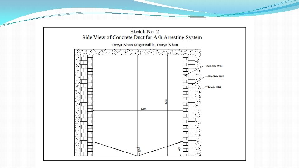
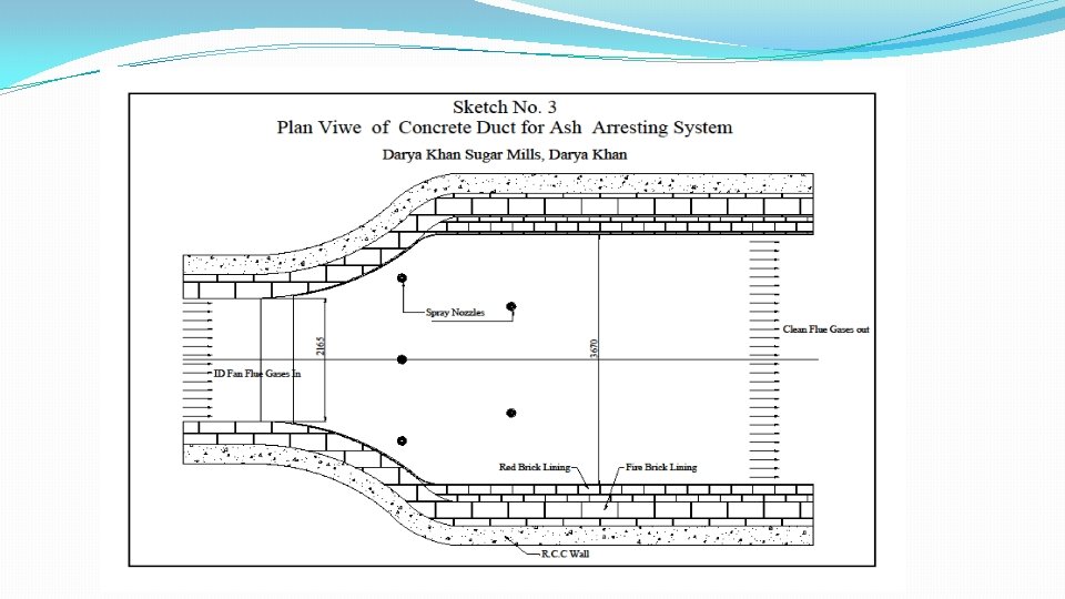
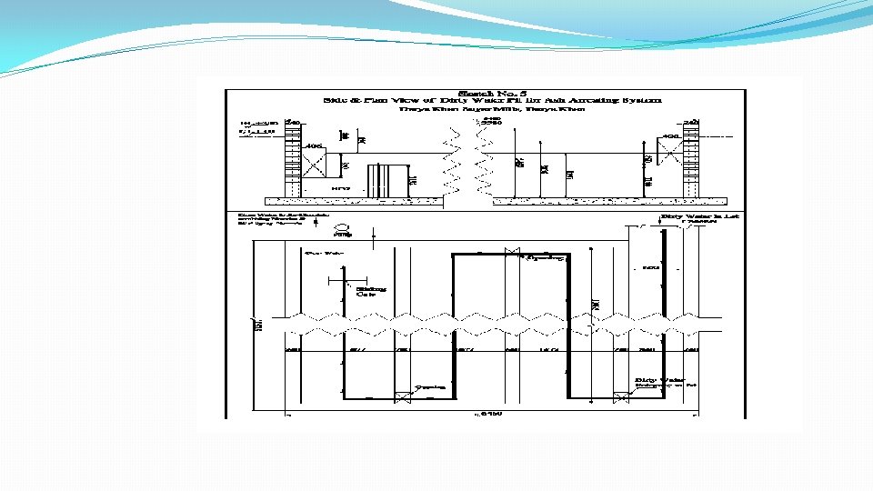
3. Material and Method: The Ash arresting System made with erection of the 80 Tons Boiler, included concrete duct, S. S mist spray nozzles fixed at the roof top, dirty water pit and recycling water pump. A. Following modifications were made at site: Referring Sketch No. 1, 2 and 3; a. b. c. d. Blocked all the nozzles except 5 nos. at the top roof of the concrete duct. Installed the top deflection plate and water spray header. Installed the angle deflection plate and water spray header. Calculated the x-area of ID Fan outlet steel duct and reduce the concrete duct x-section area accordingly with brick and cement lining. e. Made 600 mm off centre the gutter from the bottom of the top plate toward chimney to provide extra surface area for free falling the entrapped ash particles on angle plate. f. The ash pit as shown in Sketch #5, modified to increase the flow length of the dirty water for natural separation and settling of dust particles from the main stream of dirty water. g. The re-cycling water pump was assigned duty to serve the both deflection plates water headers.
Steel structure was used to install the top deflection plate and angle deflection plate was laid on the brick made supporting construction.
Sketch # 4, Flow diagram of the Flue gas arresting system:
B. Flow description of the Flue gas through the Ash Arresting System: Referring the Flow diagram of Ash Arresting system Sketch # 4 a. b. c. d. e. f. g. Gas exit from the boiler, passes over the water tubes of Economizer # 2. Then gas passes through Air Pre-heater tubes. The gas exiting the Air Pre-heater, enters tangentially through guide vanes in the cones of the nos. of cyclones placed in parallel. The gas after leaving the heavy particles in cones of the cyclones exits from the top of the cyclone. The heavy dust particles leave through the bottom of the cones in a dust bin. Then the gas passes up over water tubes of Economizer # 1. The feed water 1 st passes through Economizer #1 then through #2 in cross gas flow of gas for heat recovery from gas. The gas after passing over the Economizer #1, feed to Induced Draft Fan. The ID Fan force the gas to pass through the concrete enclosed duct of the Flue Gas Ash Arresting System. The gas passing through the duct faces three water spraying arrangements:
i. ii. iii. h. 5 Nozzles fixed in the top of the duct in pattern as shown in sketch # 3. These nozzles spray mist of water from the top in tangential flow of gas. The dust particles entrapped in the mist. The entrapped dust particles strike with top deflection plate as shown in sketch # 1 and separated from the gas stream. The water is sprayed through 36 nozzles of water header on the deflection plate which scrubbed down the entrapped dust particles from the plate and also make a curtain of water in the passage of the gas underneath of the top deflection plate. Thegaswhilepassingthroughwatercurtain, re-picktheentrappedparticles, butdropthose while rising path change due to the 35 degree angle deflection plate. The water sprayed through 36 nozzles of the top header of the angle deflection plate wash down the entrapped dust particles to gutter, where these dust particles in the form of dirty water out flow through pipe to settling Pit. The clean gas leaves the Ash Arresting System and travels to Boiler Chimney.
j. The dead slow speed of dirty water forced the gravity settling of dust particles in the bottom of the pit channels. At the last end of the 3 rd channel water collection pit is made, where lift /hrpump 150 of arresting system. The clean pit water is recycled through the both deflection plate headers. k. The settled ash in the pit is manually evacuated as per demand. In 1 st running season of 89 days length, the pit was cleaned once at the end of the season. C. The Type and Water Quantity: a. Water type: i. ii. The water from over head water service tank is sprayed through the roof top fixed mist nozzles. The clean pit water is sprayed and recycled through the both deflection plate headers.
b. Water Quantity: I Ii Over head tank water for mist nozzles Sprayed through top header of top deflection plate 0. 7 tons/hr 44. 0 tons/hr Iii Sprayed through top header of angle deflection plate 45. 0 tons/hr Total water quantity for the System 89. 7 tons/hr, 89700 kg/hr The over head water flow through top roof fixed nozzles, serve as make up water for the system. The re-cycling water can also make up through fresh water connection in the suction pit of the recycling water pump. The surplus water from the system can also out flow through pit pump delivery. D. Operation of the Ash Arresting System: All the modification/ erection work was completed in the offseason 2018. The system was put in operation at the start of the season 2018 -19. Except minor adjustments in quantity of spraying and re-cycling water during trial run, no thing was done during operation for the Boiler for entire length of season 2018 -19. The exit gas from the Boiler chimney turned to contamination free white vapours as showed in Pic # 1. Mill colony residents and surround area residents showed happiness on the operation of the Ash Arresting System at 80 tons Boiler. About 5 % increase in load was observed for ID Fan drive due to the density increase of gas as carrying water vapours. Inner inspections of the system duct were made during stop operation of Boiler due to Milling shut down for various reasons.
PIC#1, Boiler Chimney Emitting Clean Gas to Atmosphere
E. Flue Gas and Spraying Water Ratio: Referring to the Table No. 2, 1 kg Bagasse on combustion produce 3. 3129 m 3 of flue gas with 23. 7 % excess air. For semi auto operation of the boiler control at Darya Khan, we take 5 % excess volume of gas , which makes it 3. 478 m 3 per kg of Bagasse. Taking 1 ton Bagasse consumption to produce 2. 2 tons steam of 25 bar and 350 OC at Boiler. At average load of 76 tons per hr, the Boiler consumed 34. 55 tons/hr Bagasse and produced 120165 m 3 gas per hr. The ratio of gas to spraying water: 120165/ 89700= 1. 34 m 3 gas /kg water
Table #1 Typical Bagasse Analysis Sr. No. A 1 2 3 4 5 6 7 B 1 2 3 4 5 6 7 Description Proximate Analysis Moisture Fixed Carbon Volatile Matter Ash Total Brix GCV in Kj/Kg NCV in Kj/Kg Ultimate Analysis Moisture Carbon Hydrogen Nitrogen Total Sulphur Oxygen Ash Total Dry Ash free in % 12. 94 87. 06 100. 00 AS Fired in % 52. 00 5. 95 40. 05 2. 00 100. 00 2. 00 8956 7130 47. 89 5. 92 0. 33 0. 05 45. 81 100. 00 Ref: Table 27. 1/Page 620/Cane Sugar Engineering, Perter Rein 2007 52. 00 22. 04 2. 72 0. 15 0. 02 21. 07 2. 00 100. 00
Table # 2 Combustion Reaction of Bagasse and Production of Flue Gases Sr. # Constituent Symbols Parts by Mass in Kg/Kg 1 2 3 4 5 6 7 8 9 10 11 Carbon C 0. 2132 Carbon Loss C 0. 0004 C Loss C 0. 0068 Hydrogen H 2 0. 0272 Sulfur S 0. 0002 Nitrogen N 2 0. 0011 NO 2 0. 0004 Oxygen O 2 0. 2107 Argon Ar 0. 000 Water H 2 O 0. 5200 Ash 0. 0200 Total 1. 000 Oxygen in Fuel, Kg/Kg fuel Oxygen required, Kg/Kg fuel Stoichiometric mass of dry air required, Kg/Kg fuel Stoichiometric dry gas CO 2 Excess air Mass of O 2 required In Kg/Kg Products 0. 5680 0. 0005 CO 2 CO C H 2 O SO 2 NO 2 0. 2159 0. 0002 0. 0005 Ar H 2 O 0. 7851 0. 2107 0. 5744 2. 4812 20. 81 % 23. 70 % Total Mass of Gaseous product in Kg/Kg 0. 7812 0. 0009 Volume of Wet Dry gas Volume product in of Product in m 3/kg m 3/Kg 0. 3976 0. 0007 0. 2431 0. 0004 1. 8761 0. 0009 0. 3024 0. 0001 1. 4934 0. 0007 0. 0318 0. 5200 0. 0178 0. 6469 0. 0178 3. 4544 2. 8696 1. 9103 0. 5880 4. 0424 0. 4533 3. 3129 0. 4533 2. 3636
Results: Kg of flue gas/Kg Bagasse (fuel) m 3 of wet flue gas/Kg Bagasse(fuel) Dry gas CO 2 in % Wet gas O 2 in % 4. 04 3. 3129 16. 82 2. 88 Ref: Table 27. 4/Page 623/Cane Sugar Engineering, Perter Rein 2007
4. Results and Discussion: The Environment Protection Agency Pakistan (EPA) set the standard of 500 mg/Nm 3 for maximum particulate carry with Boiler flue gas. As Bagasse has minimum level of sulphur of 0. 05 %, So So 2 gas percentage in flue gas of Bagasse fired boiler is not a issue of EPA. The Wet Ash Arresting System was installed in off season 2018 and operated with excellent performance in season 2018 -19. No technical and human right issue was raised through out the season as emittied gas from Boiler chimney turned to water vapours as shown in Pic #1. In crushing season 2017 -18 , EPA experts tested the smoke sample of 80 tons Boiler of DKSM and raised no complaint, whereas the Boiler was operated with only cyclone ash arresting system. In crushing season 2018 -19, DKSM installed and operate Wet Ash Arresting System, EPA raised no complaint against DKSM. 5. Acknowledgement Author pay thanks the Bestow of ALLAH SUBHANA HU TAALA for completion and success full operation of the Wet Ash Arresting System at Darya Khan Sugar Mills. Author also acknowledged the assistance and dedicated efforts of Mushtaq Ali Shad, Technical Manager, Safdar Hussain Shah, Chief Engr. (Boiler) and S. Saqib Saeed Saadi, Sr. Engr. for the design, erection and operation of the system.
THANK YOU!