Signals ELECTROMAGNETIC INDUCTION Faradays Law Lenzs Law Time


 electrical energy to")


 of upper atmosphere")

 Propagation • Transmitting and receiving antennas must be within line of sight")


 d = separation distance (in meters) c")
")


- Slides: 58
Signals
ELECTROMAGNETIC INDUCTION
Faraday’s Law& Lenz’s Law
Time Domain REPRESENTATION OF SIGNALS
Signal, amplitude and phase
Amplitude of signal as a function of phase
Hellschreiber painted text Each character is sent on a double line, improving the ability to read the characters under a noisy channel, communicated as a series of dots. A black (white ) dot is coded as 900 (980) Hertz tone. The tones modulate in amplitude a RF carrier. Is signaling analog or digital? Is the data analog or digital?
FREQUENCY DOMAIN REPRESENTATION OF SIGNALS
The square signal and its generation usingenerated signals.
Frequency domain representation of the square signal
A square pulse of length x second, from time -x/2 to time x/2
Spectrum of a square pulse of length x second, from time -x/2 to time x/2
ANTENNAS
What is an antenna? • A converter: – Transmitter: radio-frequency (RF) electrical energy to electromagnetic energy – Receiver: electromagnetic energy and to electrical energy • Two-way communications: – two antennas or – single transmission/reception antenna
Wavelength • In free space, distance traveled during one period • Velocity: speed of light (c)
Antenna Gain – Output power, in a particular direction, relative to that produced by an isotropic antenna – A ratio of power. S – In d. Bi:
Directivity and Gain Flashlight Analogy
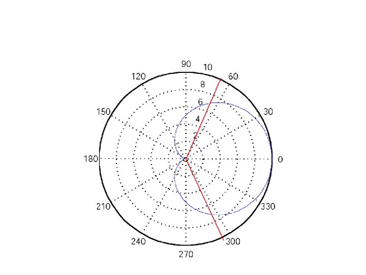
Radiation Pattern
Types of Antennas • Isotropic • Idealized, point in space • Radiates power equally in all directions • Dipole • Half-wave dipole (Hertz antenna) • Omnidirectional • 2 D isotropic • Vertical, 1/4 –wave monopole, Marconi, groundplane • Directional • Yagi • Parabolic reflective
Antenna Patterns
Geometry of the Dipole
Radiation Pattern of the Dipole
Geometry of the Groundplane
Radiation pattern of the Groundplane
Geometry of the Yagi
Radiation pattern of the Yagi
Beamwidth
What is the beamwidth?
PROPAGATION
Propagation Modes • Ground-wave • Sky-wave • Line-of-sight
Ground Wave Propagation
Ground Wave Propagation • Follows contour of the earth • Diffraction: bending of waves around obstacles • Example: AM radio (day time) • Long distances are possible, but high power required
Sky Wave Propagation
Sky Wave Propagation • Signal reflected from ionized layer (ionized atoms) of upper atmosphere (160 to 500 km) back down to earth • Signal can travel a number of hops, back and forth between ionosphere and earth’s surface • Reflection effect caused by refraction – Refraction: medium of one density to a medium of another density causes bending of waves • Examples – Amateur radio, CB radio, short wave broadcast • Drawback – Not reliable, conditions vary considerably as a function of day time and time of the year
Line-of-Sight Propagation
Line-of-Sight (LOS) Propagation • Transmitting and receiving antennas must be within line of sight • Terrestrial communications • antennas within effective line of sight • Satellite communications – signal from • 30 MHz (downlink) • 150 MHz (uplink, not reflected by ionosphere)
LOS Propagation Distance • Optical line of sight • Effective, or radio, line of sight • d = distance between antenna and horizon (km) • h = antenna height (m) • K = adjustment factor to account for refraction, rule of thumb K = 4/3
LOS Propagation Distance • Maximum distance between two antennas for LOS propagation: • h 1 = height of antenna one • h 2 = height of antenna two
Channel Capacity • Nyquist • Shannon
Impairments • • Attenuation and attenuation distortion Free space loss Noise Atmospheric absorption Multipath Refraction Thermal noise
Attenuation • Signal strength drops with distance and frequency • Received signal strength must be: – at least equal to receiver sensitivity – (several times) higher than noise errorless reception
Free Space Loss = wavelength (in meters) d = separation distance (in meters) c = speed of light (3 × 10⁸ m/s)
Free Space Loss (d. B)
Free space loss at 2. 4 GHz and 5 GHz as a function of distance
RSS as a function of distance
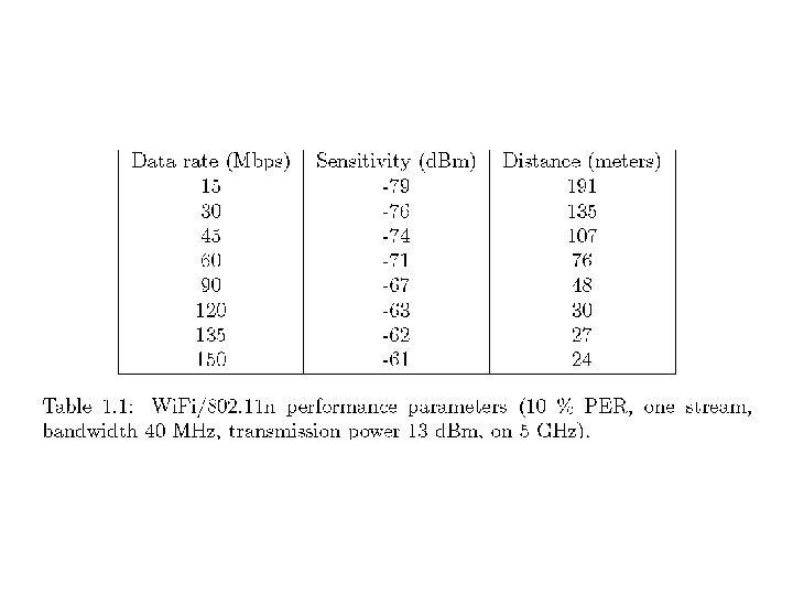
Range as a function of the data rate for Wi. Fi/802. 11 n
Percentage of total area as a function of the data rate
Percentage of airtime as a function of the data rate Under the fairness assumption.
Solar Activity • Solar storm headed to Earth but few power grid problems expected. - The Ottawa Citizen, July 13, 2012. • Massive blast of radiation from a huge solar flare headed for Earth. Solar radiation that NASA warns could temporarily disrupt satellite communications and power grids. - The Calgary Herald, July 14, 2012.
The big one.
Planetary A index during the month of July 2012.
Coronal Mass Ejection of July 12, 2102
WIRELESS DIGITAL COMMUNICATIONS MYTHS
1. Digital communications is superior to wireless analog communications! • Current consumption, analog is better. • Digital modulation is more complex and needs more resources (circuitry or computational).
2. Digital voice is better than analog voice!