Syafruddin Hasan Power Flow Diagram Figure Motor energy


:")


 The stator resistance was measured directly")


- Slides: 18
Syafruddin Hasan
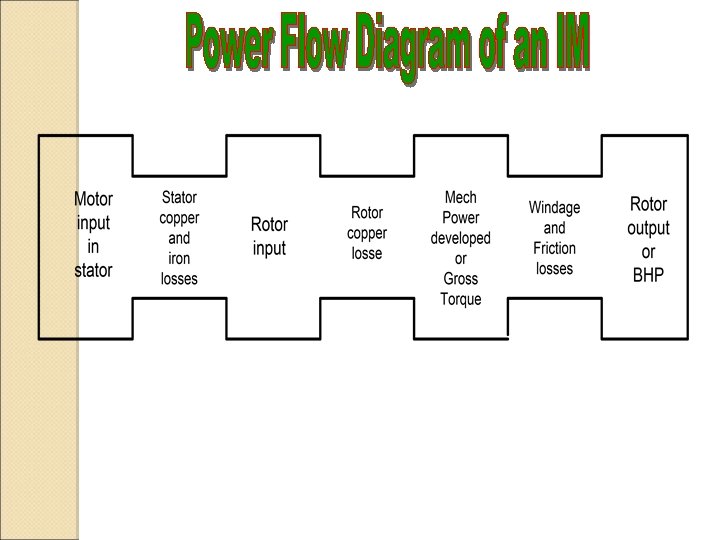
Power Flow Diagram Figure Motor energy balance flow diagram.
Induction Motors � Figure � The shows the energy balance in a motor. supply power is: � The power transferred through the air gap by the magnetic coupling is the input power (Psup) minus the stator copper loss and the magnetizing (stator iron) loss. � The electrically developed power (Pdv) is the difference between the air gap power (Pag) and rotor copper loss.
Induction Motors � The electrically developed power can be computed from the power dissipated in the second term of rotor resistance: � The subtraction of the mechanical ventilation and friction losses (Pmloss) from the developed power gives the mechanical output power
Power and Torque in an IM From Fig. 7 -12 Input current : I 1 = VΦ / Zeq Pcu Stator: Pscl = 3 I 12 R 1 Core Losses : Pcore = 3 E 12 Gc Air-gap power : PAG = Pin – Pscl – Pcore = 3 I 22 R 2/s Pcu Rotor: PRcl = 3 IR 2 RR = 3 I 22 R 2 Note PAG : Pconv : PRCL = 1 : (1 -s) : S Example 7 -3
Induction Motors � The motor efficiency: � Motor torque (shaft load torque):
Equivalent Circuit Figure Single-phase equivalent circuit of a threephase induction motor.
Induction Motors Figure Modified equivalent circuit of a three-phase induction motor. The rotor impedance is transferred to the stator side. This eliminates the transformer
Induction Motors Figure Simplified equivalent circuit of a three-phase induction motor.
Induction Motors � The last modification of the equivalent circuit is the separation of the rotor resistance into two parts: � The obtained resistance represents the outgoing mechanical power
Blocked-Rotor test (cont…) The stator resistance was measured directly
IM Design Classes NEMA & IEC : Class A: normal Tst, normal Ist, normal S Class B: normal Tst, low Ist, low S Class C: high Tst, low Ist, low S Class D: high Tst, low Ist, high S Class E: low Tst, normal Ist, low S Class F: low Tst, low Ist, normal S
Starting Induction Motors Problems : - High Starting current - Low starting torque Determining of Istart � Read the rated voltage, hp and code letter from name plate. � Starting apparent power : Sstart = (rated hp)(code letter factor) Istart = Sstart / √ 3 VT Example 7 -7
Q U I Z 04 -10 -2005 � 1. Why the circuit equivalent of an induction motor can be approached by equivalent circuit of a transformer and draw it � 2. The output of a 3 phase induction motor is 9 k. W. Rotor copper losses is 0. 5 k. W. Motor runs at 5 % of slip. Stator loss is 0. 75 k. W a). Calculate the mechanical power that converter by this motor b). Determine the input power c). Calculate the efficiency
Speed Control of IM Ø Ø ns = 120 f / p by changing the electrical frequency (f) by changing the number of poles (p) (1) The methode of consequent poles (2) Multiple stator windings Ø Ø Ø by changing the line voltage: n proportional to V 2 by changing the rotor resistance Solid-state IM drives
Motor Protection �Over Current Protection �Over Load Protection
IM Ratings 1. 2. 3. 4. 5. 6. 7. 8. 9. Output power Voltage Current Power Factor Speed Nominal efficiency NEMA design Class Starting Code Service Factor (SF)