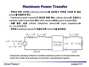
SAE J 3068 Meeting EV Power Transfer using
- Slides: 19
SAE J 3068 Meeting EV Power Transfer using Three-phase Capable Coupler Rodney Mc. Gee Thursday, June 26, 2014 10: 00 AM EDT Web. Ex Meeting SAE J 3068 1
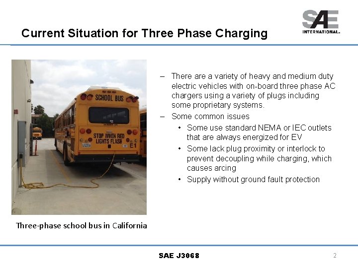
Current Situation for Three Phase Charging – There a variety of heavy and medium duty electric vehicles with on-board three phase AC chargers using a variety of plugs including some proprietary systems. – Some common issues • Some use standard NEMA or IEC outlets that are always energized for EV • Some lack plug proximity or interlock to prevent decoupling while charging, which causes arcing • Supply without ground fault protection Three-phase school bus in California SAE J 3068 2
Scope of J 3068 – The SAE has authorized a document for three-phase AC charging for electric vehicles – Scope This document covers the general physical, electrical, functional, testing, and performance requirements for conductive power transfer to an electric vehicle using a coupler capable of, but not limited to, transferring three-phase AC power. It defines a conductive power transfer method including the digital communication system. It also covers the functional and dimensional requirements for the vehicle inlet, supply equipment outlet, and mating housings and contacts. – Targeted towards charging at commercial and industrial locations or other places where three-phase power is available and preferred. SAE J 3068 3
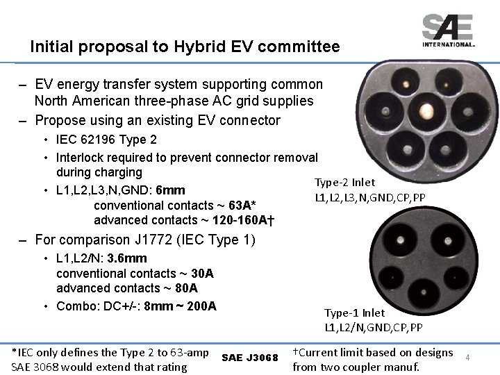
Initial proposal to Hybrid EV committee – EV energy transfer system supporting common North American three-phase AC grid supplies – Propose using an existing EV connector • IEC 62196 Type 2 • Interlock required to prevent connector removal during charging Type-2 Inlet • L 1, L 2, L 3, N, GND: 6 mm L 1, L 2, L 3, N, GND, CP, PP conventional contacts ~ 63 A* advanced contacts ~ 120 -160 A† – For comparison J 1772 (IEC Type 1) • L 1, L 2/N: 3. 6 mm conventional contacts ~ 30 A advanced contacts ~ 80 A • Combo: DC+/-: 8 mm ~ 200 A *IEC only defines the Type 2 to 63 -amp SAE 3068 would extend that rating Type-1 Inlet L 1, L 2/N, GND, CP, PP SAE J 3068 †Current limit based on designs from two coupler manuf. 4
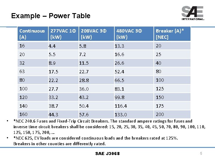
Example – Power Table Continuous (A) • • 277 VAC 1Φ 208 VAC 3Φ (k. W) 480 VAC 3Φ (k. W) Breaker (A)* [NEC] 16 4. 4 5. 8 13. 3 20 20 5. 5 7. 2 16. 6 25 32 8. 9 11. 5 26. 6 40 63 17. 5 22. 7 52. 4 80 80 22. 2 28. 8 66. 5 100 27. 7 36. 0 83. 1 125 120 33. 2 43. 2 99. 8 150 140 38. 7 50. 4 116. 4 175 160 44. 3 57. 6 133. 0 200 *NEC 240. 6 Fuses and Fixed-Trip Circuit Breakers. The standard ampere ratings for fuses and inverse time circuit breakers shall be considered: 15, 20, 25, 30, 35, 40, 45, 50, 70, 80, 90, 100, 110, 125, 150, 175, 200, … *NEC 625, EV loads are considered continuous loads and the breakers rated at 125%. Breakers in other counties are differently rated. SAE J 3068 5
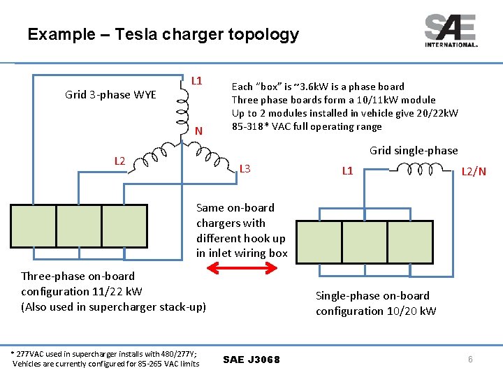
Example – Tesla charger topology Grid 3 -phase WYE L 1 N Each “box” is ~3. 6 k. W is a phase board Three phase boards form a 10/11 k. W module Up to 2 modules installed in vehicle give 20/22 k. W 85 -318* VAC full operating range Grid single-phase L 2 L 3 L 1 L 2/N Same on-board chargers with different hook up in inlet wiring box Three-phase on-board configuration 11/22 k. W (Also used in supercharger stack-up) * 277 VAC used in supercharger installs with 480/277 Y; Vehicles are currently configured for 85 -265 VAC limits Single-phase on-board configuration 10/20 k. W SAE J 3068 6
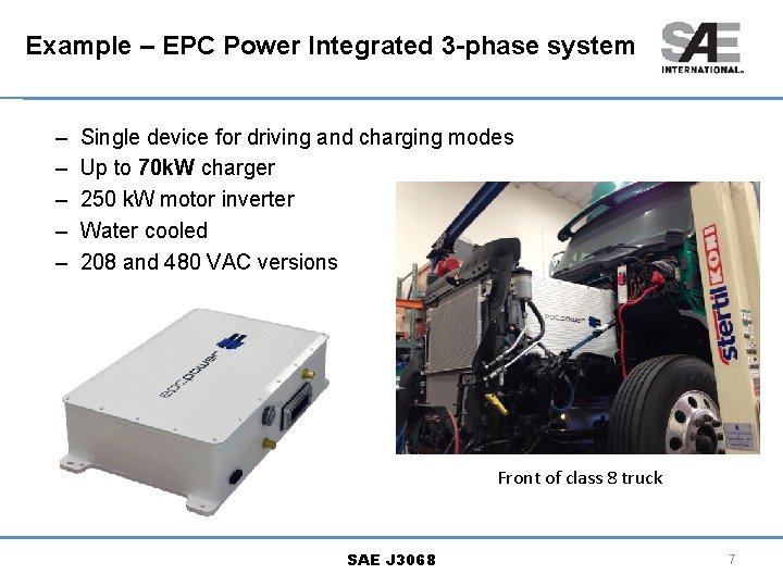
Example – EPC Power Integrated 3 -phase system – – – Single device for driving and charging modes Up to 70 k. W charger 250 k. W motor inverter Water cooled 208 and 480 VAC versions Front of class 8 truck SAE J 3068 7
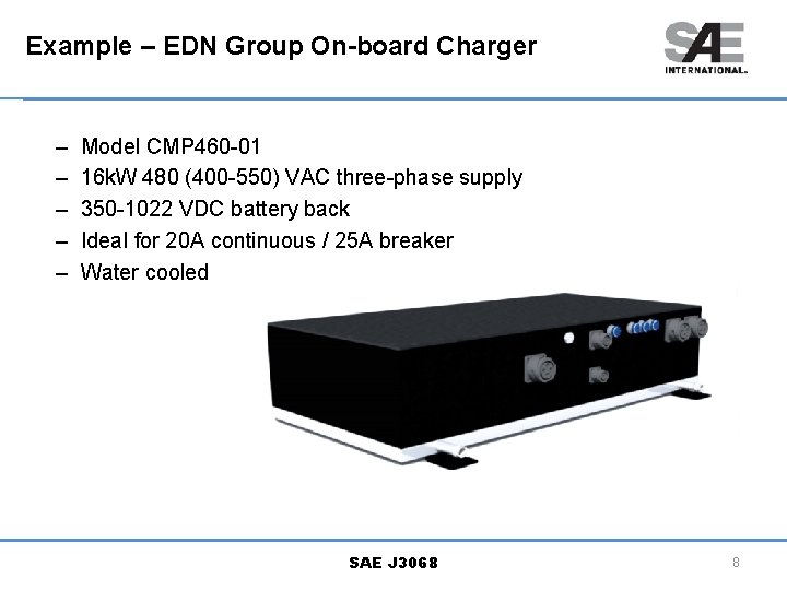
Example – EDN Group On-board Charger – – – Model CMP 460 -01 16 k. W 480 (400 -550) VAC three-phase supply 350 -1022 VDC battery back Ideal for 20 A continuous / 25 A breaker Water cooled SAE J 3068 8
Backup SAE J 3068 9
NFPA 70 – NEC – Current definitions and scope seem fine • “ 625. 4 Voltages. Unless other voltages are specified, the nominal AC system voltages of 120, 120/240, 208 Y/120, 240, 480 Y/277, 480, 600 Y/347, and 600 volts. ” – Need to identify any possible issues with current code • No major issues identified yet • NEC 2017 is open for public changes this summer into early fall SAE J 3068 10
UL 2594 1 st edition – Need to review this document for needed changes • So far so good; needs a more careful read through – Scope: • 1. 1 This Standard covers conductive electric vehicle (EV) supply equipment with a primary source voltage of 600 V ac or less, with a frequency of 60 Hz, and intended to provide ac power to an electric vehicle with an on-board charging unit. This Standard covers electric vehicle supply equipment intended for use where ventilation is not required. – Electric vehicle supply equipment covered by this Standard includes: • … • f) Permanent EV Charging Station – Rated 600 Vac maximum, intended for indoor/ outdoor use; or • g) Permanent EV Power Outlet – Rated 600 Vac maximum, intended for indoor/ outdoor use. – 6. 2 EV charging stations • 6. 2. 1 EV charging stations shall be provided with an EV receptacle or an EV connector on the vehicle side of the device. SAE J 3068 11
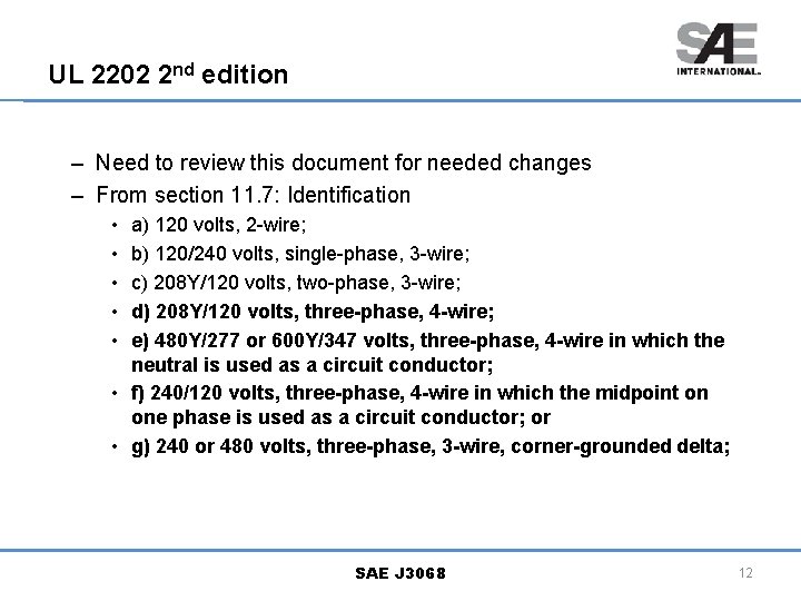
UL 2202 2 nd edition – Need to review this document for needed changes – From section 11. 7: Identification • • • a) 120 volts, 2 -wire; b) 120/240 volts, single-phase, 3 -wire; c) 208 Y/120 volts, two-phase, 3 -wire; d) 208 Y/120 volts, three-phase, 4 -wire; e) 480 Y/277 or 600 Y/347 volts, three-phase, 4 -wire in which the neutral is used as a circuit conductor; • f) 240/120 volts, three-phase, 4 -wire in which the midpoint on one phase is used as a circuit conductor; or • g) 240 or 480 volts, three-phase, 3 -wire, corner-grounded delta; SAE J 3068 12
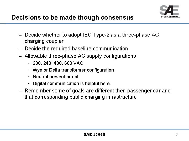
Decisions to be made though consensus – Decide whether to adopt IEC Type-2 as a three-phase AC charging coupler – Decide the required baseline communication – Allowable three-phase AC supply configurations • • 208, 240, 480, 600 VAC Wye or Delta transformer configuration Neutral present or not Digital communication is helpful here. – Remember some of goals are different then passenger car and that corresponding public charging infrastructure SAE J 3068 13
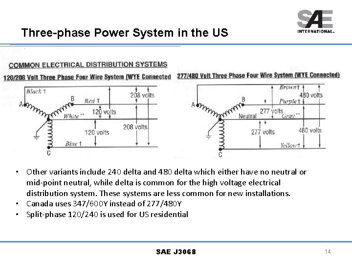
Three-phase Power System in the US • Other variants include 240 delta and 480 delta which either have no neutral or mid-point neutral, while delta is common for the high voltage electrical distribution system. These systems are less common for new installations. • Canada uses 347/600 Y instead of 277/480 Y • Split-phase 120/240 is used for US residential SAE J 3068 14
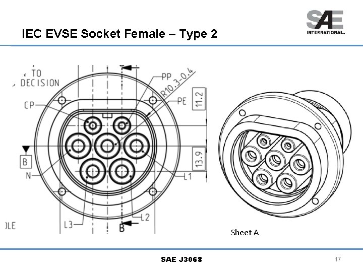
IEC Type 2 Coupler System SAE J 3068 15
Can SAE make normative references in a document to IEC standards? – Yes, an example of this is J 1113/1: • “By reference, IEC CISPR 25 is adopted as the standard for the measurement of component emissions. In the event that an amendment is made or a new edition is published, the new IEC document shall become part of this standard six months after the publication of the IEC document. ” • “SAE reserves the right to identify exceptions to the published IEC document with the exceptions to be documented in SAE J 1113 -41. ” – This seems like a good approach to take if we decide to adopt any parts of the J 3068 system that are already defined in the IEC. – Identify places where we need to differ because of national rules, codes, and our requirements SAE J 3068 16
IEC EVSE Socket Female – Type 2 Sheet A SAE J 3068 17
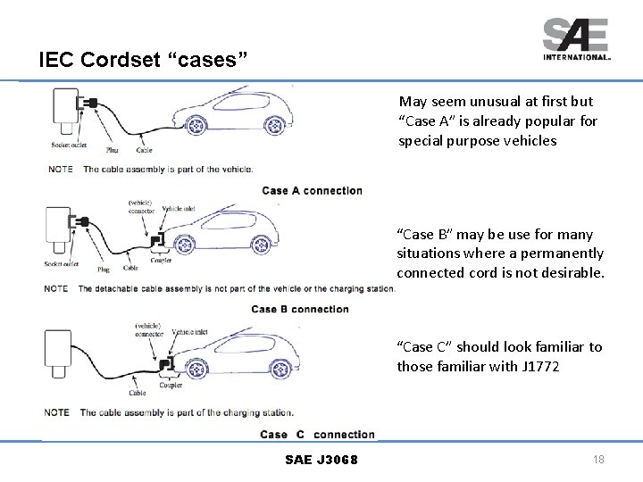
IEC Cordset “cases” May seem unusual at first but “Case A” is already popular for special purpose vehicles “Case B” may be use for many situations where a permanently connected cord is not desirable. “Case C” should look familiar to those familiar with J 1772 SAE J 3068 18
Changes need from IEC 62196 -2 Type-2 – Allow nominal voltages up to 600 VAC (500 VAC limit in IEC) – Add a resistor coding for fixed “Case C” cordset. – Increase minimum “packing room” to allow for heavier duty housings and bigger wires in the future SAE J 3068 19