Maximum Power Transfer matching network power Maximum power


 따라서")

 Instantaneous power (1) 단위 P : Watt, Q : VAR (Volt-Amp")
 Instantaneous power (3) power factor reactive factor power factor 값을 알")


 + – I 1 Zs Vs a c R 1 b")
 전압 부호 결정 : 2차 측 open,")
 전압 부호 결정 : 2차 측 open,")
 M a + m a’ n a’")

- Slides: 30
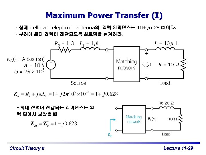
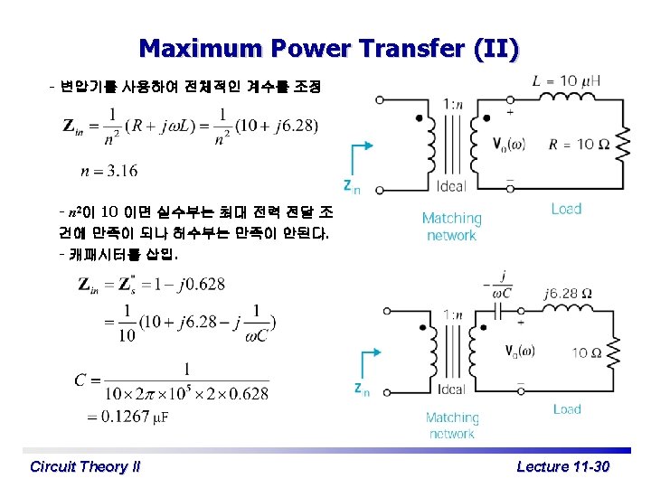
Maximum Power Transfer - 전원과 부하 사이에 matching network을 삽입해서 부하에 가능한 한 많은 power를 전달하게 한다. - Maximum power transfer의 중요한 응용 예는 cellular phone의 연결이나 wireless radio transmitter에서 cell’s antenna로의 power transfer이다. - 예를 들면, 실제 cellular telephone antenna의 input impedance는 10+j 6. 28 W 이 다. - 부하에 maximum power가 전달되도록 network을 설계하라. Design the matching network to transfer maximum power to the load where the load is the model of an antenna of a wireless communication system. Circuit Theory II Lecture 11 -1
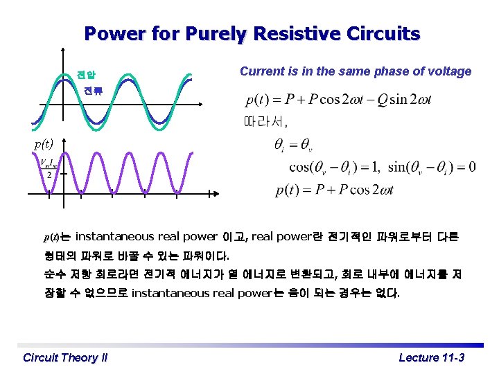
Sinusoidal Steady-State Power Calculations Instantaneous power + v – i i v - i - v Circuit Theory II Average power t Lecture 11 -2
Power for Purely Inductive Circuits 전류 전압 Current lags voltage by 90º p(t) 따라서 Average power는 영이므로 에너지의 변환은 없다. Instantaneous power는 reactive power이고 회로에서 부하와 전원사이를 오간다. p > 0 이면 전원 부하. p < 0 이면 전원 부하. Circuit Theory II Lecture 11 -4
Power for Purely Capacitive Circuits 전류 전압 Current leads voltage by 90º 따라서 Average power는 영이므로 에너지의 변환은 없다. Instantaneous power는 reactive power이고 회로에서 부하와 전원사이를 오간다. p > 0 이면 전원 부하. p < 0 이면 전원 부하. Circuit Theory II Lecture 11 -5
Reactive Power (I) Instantaneous power (1) 단위 P : Watt, Q : VAR (Volt-Amp Reactive) (2) 전류를 기준으로 하면 Inductor는 이므로 Q > 0 이때 Inductor는 magnetizing vars를 흡수한다고 한다. Capacitor는 이므로 Q < 0 이때 Capacitor는 magnetizing vars를 전달한다고 한다. Circuit Theory II Lecture 11 -6
Reactive Power (II) Instantaneous power (3) power factor reactive factor power factor 값을 알 경우 reactive factor 의 값을 알 수 있어도 부호를 결정할 수 없다. lagging power factor 라 하면 inductive 이므로 Q 는 양이고, leading power factor 라 하면 capacitive 이므로 Q 는 음이 된다. Circuit Theory II Lecture 11 -7
Power Calculations 파워를 복소수로 나타낼 수 있 다. S 를 정리하면 + Circuit – Phasor voltage and circuit 따라서, Circuit Theory II Lecture 11 -9
Alternate Forms for Complex Power Z를 사용해서 S를 표현하자. 이므로 + Z 따라서, – 또한 Circuit Theory II 이므로 Lecture 11 -10
Maximum Power Transfer Sinusoidal steady state 회로에서 최대 average power를 전달하려면 즉 부하 임피던스는 전원의 (테브난) 임피던스의 complex conjugate가 되어야 최대 전력이 전달된 다. Circuit Theory II Lecture 11 -11
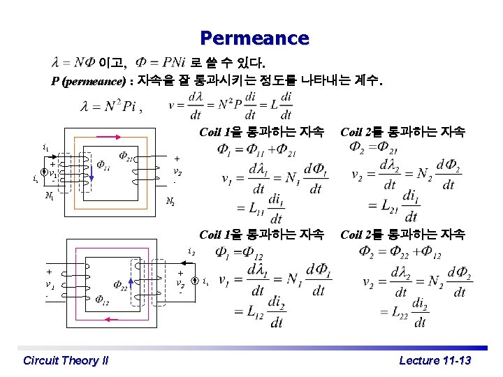
Self and Mutual Inductance Lij ij + λj _ ii + λi _ xj ≡ λi ij (이때 ij외의 전류는 영) Lij에서 i = j 이면 self inductance, i ≠ j 이면 mutual inductance 이다. 즉, self inductance는 자기 코일의 전류에 의해 발생하는 쇄 교 자속에 의한 것이고, mutual inductance는 남의 코일의 전류에 의해 발생하는 쇄교 자속에 의한 것이다. xi 코일이 두개라면 L 11 , L 22 : self inductance, L 12 , L 21 : mutual inductance Circuit Theory II Lecture 11 -12
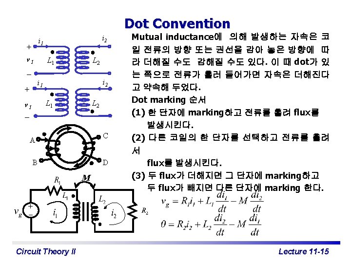
Dot Convention - Example Current entering the dotted terminal of one coil produces a voltage that is sensed positively at the dotted terminal of the second coil. Current entering the undotted terminal of one coil produces a voltage that is sensed positively at the undotted terminal of the second coil. Circuit Theory II Lecture 11 -16
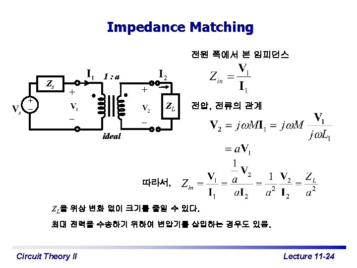
Linear Transformer I 1 Zs + V – s a c R 1 R 2 b I 2 ZL d Load Source - Transformer : Magnetic coupling을 이용하는 대표적인 기기 - Transformer는 직류 전류나 전압은 전달하지 않으므로 교류만을 분리할 때도 이용 - 선형은 magnetic flux가 전류에 비례한다는 의미 - Sinusoidal steady-state를 해석 ab 단자에서 본 impedance 1차측 2차측 정리하면 : Reflected impedance : Total self-impedance 전원 단자에서 본 impedance Scale Circuit Theory II , reactive : 부호 바뀜 Lecture 11 -18
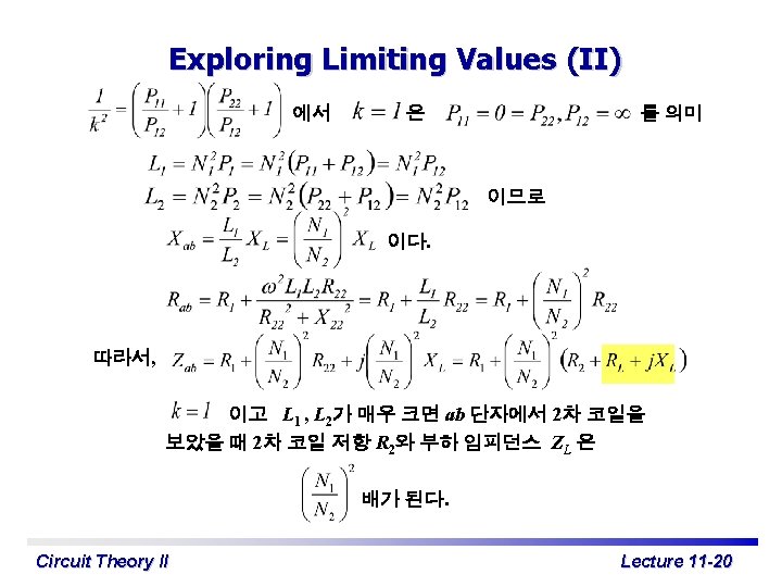
Exploring Limiting Values(I) + – I 1 Zs Vs a c R 1 b R 2 I 2 실제 변압기에서 L 1, L 2는 매우 크고 k는 ZL 거의 1 에 가깝다. 이럴 때의 Zab를 구해보자. d Load Source 여기서 이면 여기서 Circuit Theory II Lecture 11 -19
Polarity of Voltage and Current Ratio (I) 전압 부호 결정 : 2차 측 open, 전류 부호 결정 : 2차 측 short. + – + – 1: a A + – C D B – + – E F 다음의 조합으로 회로를 결정할 수 있다. dot : A, B 전압: C, D 전류: E, F Case study (1) dot : B, 전압: D, 전류: E open : + short : Circuit Theory II Lecture 11 -22
Polarity of Voltage and Current Ratio (II) 전압 부호 결정 : 2차 측 open, 전류 부호 결정 : 2차 측 short. + – A + – C D B – + E F 다음의 조합으로 회로를 결정할 수 있다. dot : A, B 전압: C, D 전류: E, F Case study (2) dot : B, 전압 : C, 전류 : F open : + – Circuit Theory II 1: a + – short : Lecture 11 -23
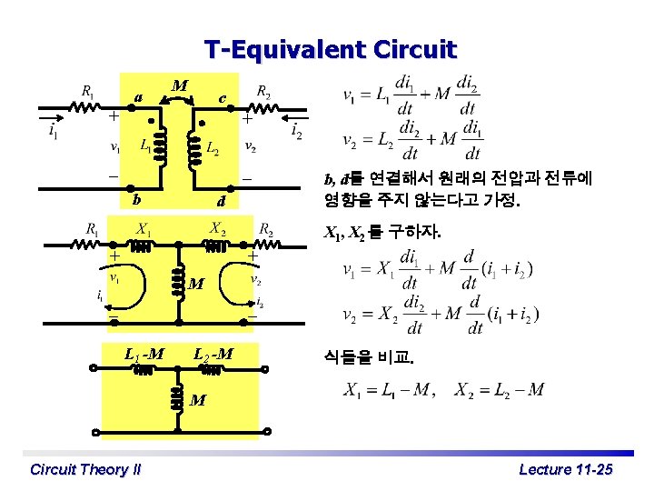
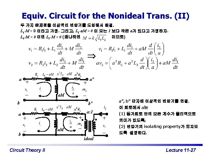
Equivalent Circuit for the Nonideal Transf. (I) M a + m a’ n a’ a + m n M b – – b b’ b’ b b b’ b’ - Analysis of Electric Circuits, E. Brenner, Mc. Graw-Hill, 1967 (pp. 565 -568). T형 등가회로의 두 가지 문제점. (1) L 1 -M 또는 L 2 -M 이 음수가 될 수 있음. 계산 시에는 문제가 없으나 물리적으로 negative inductance는 없음. (2) 변압기의 성질인 분리가 안됨. Circuit Theory II Lecture 11 -26
Applications – Speaker Systems - 음을 충실히 재생하기 위하여 주파 수 대역별로 스피커를 사용. - Woofer: 20 Hz ~ 300 Hz. - Midrange: 100 Hz ~ 5 k. Hz. - Tweeter: 2 k. Hz ~ 25 k. Hz. - Crossover speaker system : parallel network with speakers. - 예를 들어, 1. 4 k. Hz 에서 midrange speaker 는 4. 5 W, woofer 는 1 W, tweeter 는 1. 3 W 정도를 소모한다. Crossover speaker system Circuit Theory II Lecture 11 -28