RADAR ANTENNA Functions of Radar Antenna Transducer Concentrates


- Slides: 15

RADAR ANTENNA

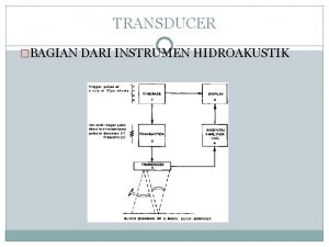
Functions of Radar Antenna • Transducer. • Concentrates the radiated energy in one direction (Gain). • Collects echo energy scattered back to radar (Aperture). • Measures the angle of arrival of echo. • Acts as a spatial filter to separate targets in angle(spatial) domain. • Provides volumetric coverage of the radar. • Establishes the time between radar observations of a target. (Revisit time)

• Larger antenna : Better radar performance, smaller transmitter, less power. • Transmitting antenna gain and receiving effective aperture proportional to one another. • All radar antennas are directive and beam steerable.

Antenna parameters 1. 2. 3. 4. 5. 6. 7. Directive Gain. Power gain Radiation pattern Effective aperture Side lobe radiation Aperture efficiency Polarization.

Directive Gain • The directive gain of a transmitting antenna may be defined as,

Power Gain • Power gain G, • Equivalent definition is • The power gain and directiven gain are related by radiation efficiency ( r). G = r. GD

• Power gain is used in radar range equation since it includes the dissipative losses of antenna itself. • GD > G • Gain is always defined in terms of transmitting antenna. • Accuracy is about 0. 5 d. B.

Antenna Radiation Pattern • Relative gain Vs Angle. • Vestigial lobes.

Effective Aperture • The effective aperture of an antenna Ae is the area presented to the radiated or received signal. • The gain is related to the effective area by the following relationship: λ = wave length Ae = effective antenna aperture A = physical area of the antenna a = antenna aperture efficiency • The aperture efficiency depends on the distribution of the illumination across the aperture. If this is linear then a= 1. • This high efficiency is offset by the relatively high level of sidelobes obtained with linear illumination. Therefore, antennas with more practical levels of sidelobes have an antenna aperture efficiency less than one (Ae< A).

Sidelobe Radiation • The sidelobes are smaller beams that point in different directions to the main beam. These sidelobes radiate in undesired directions and can never be completely eliminated. • Lower sidelobes result the lower gain, lower aperture efficiency but beamwidth is higher. • Low antenna sidelobes are desired in radar to avoid detecting large targets when they are illuminated by the antenna sidelobes. • Any echoes in sidelobe region will not indicated by their true angle. • Low sidelobes are useful to minimize the effect of jamming, interference and to reduce the large clutters. • -23 to -28 d. B ----- SLL of Parabolic reflector • -40 to -50 d. B ----- array antennas

Aperture Efficiency • Aperture efficiency is based on the maximum radiation intensity. • If radiation efficiency is less than 1, energy is lost. Aperture efficiency is less than 1, the radiated energy is redistributed in angle rather than be dissipated. • Aperture efficiency might be reduced to obtain low SLL, shaped beams, monopulse antenna patterns.

Polarization • Most radar antennas are linearly polarized. – Air Surveillance radars --- Horizontal polarization. – Tracking radars --- Verical polarization. • Circular polarization – enhance the detectability of aircraft targets in the midst of rain.

Aperture Illumination and Aperture Blocking • Aperture illumination or current distribution is the current at a distance ‘z’ from the center of the radiating line-source antenna. • Proper illumination is required to achieve suitable radiation patterns. • An obstacle in front of an antenna can alter the effective aperture illumination and distort the radiation pattern – Aperture blocking or shadowing. • E. g : feed and its supports; nearby buildings, trees etc. ,

Effects of Aperture Blocking • Lowers the antenna gain • Raises the sidelobes : If peal SLL is -30 to -40 d. B , obstructed beam results -15 to -20 d. B SLL. • Fills in the nulls • The effect can be approximated by subtracting the pattern produced by shadow of an obstacles from the undisturbed antenna pattern. • This is feasible due to the linearity of Fourier transform that relates aperture illumination and radiation pattern.

Parabola - Reflector • All reflected rays will be parallel to the axis of the paraboloid. This gives a single reflected ray parallel to the main axis with no sidelobes. • The field leaves the feed horn with a spherical wave front. As each part of the wave front reaches the reflecting surface, it is shifted 180 degrees in phase and sent outward in parallel paths. • This is an idealized radar antenna and produces a pencil beam. • If the reflector has an elliptical shape, then it will produce a fan beam. • Surveillance radars may use two different curvatures in the horizontal and vertical planes to achieve the required pencil beam in azimuth and in elevation.
 Radar antenna parameters
 Examples of roughages for animals
 Fol
Fol Mti radar with power amplifier transmitter
 Pulse doppler radar vs mti
 Arduino ultrasonic transducer
 Ott pls-c
 Shadin fuel flow
 Is a microphone a transducer
 Photoemissive photoconductive and photovoltaic
 Basic requirements of transducer
 Example of active transducer
 Moct
Moct Piezoelectric materials ppt
 Ampere transducer
 Transducer techniques ssi
