
Chapter 6 Sensor Transducer Definition of a transducer
- Slides: 26
Chapter 6 Sensor & Transducer
Definition of a transducer Transducer is any device that converts energy in one form to energy in another. The majority either convert electrical energy to mechanical displacement or convert some nonelectrical physical quantity, such as temperature, sound or light to an electrical signal. Sensor & Transducer 2
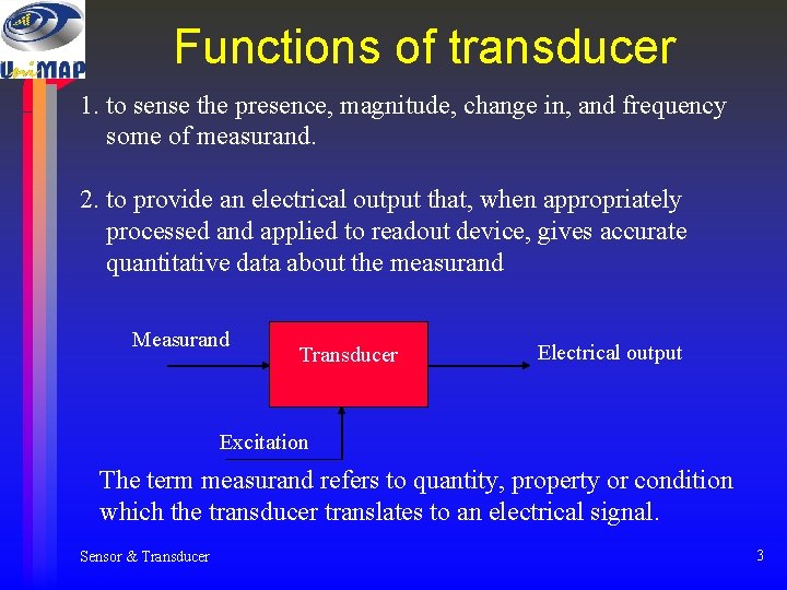
Functions of transducer 1. to sense the presence, magnitude, change in, and frequency some of measurand. 2. to provide an electrical output that, when appropriately processed and applied to readout device, gives accurate quantitative data about the measurand Measurand Transducer Electrical output Excitation The term measurand refers to quantity, property or condition which the transducer translates to an electrical signal. Sensor & Transducer 3
Classification of transducers Transducer can be classified according to their application, based primarily on the physical quantity, property, or condition that is measured. The transducer can be categories into: Passive transducer: these transducers require an external power, and their output is a measure of some variation, such resistance and capacitance. Self generating transducer: These transducers do not require an external power, and they produce analog voltage or current when stimulated by some physical form of energy. Sensor & Transducer 4
Selecting a transducers 1. 2. 3. 4. 5. 6. 7. 8. Operating range Sensitivity Frequency response and resonant frequency Environmental compatibility Minimum sensitivity measurand. Accuracy Usage and ruggedness Electrical parameter Sensor & Transducer 5
Temperature Transducers Temperature transducers can be divided into four main categories: 1. Resistance temperature detectors (RTD) 2. Thermocouples 3. Thermistor 4. Ultrasonic transducers Sensor & Transducer 6
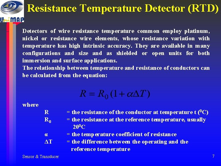
Resistance Temperature Detector (RTD) Detectors of wire resistance temperature common employ platinum, nickel or resistance wire elements, whose resistance variation with temperature has high intrinsic accuracy. They are available in many configurations and size and as shielded or open units for both immersion and surface applications. The relationship between temperature and resistance of conductors can be calculated from the equation: where R R 0 α ΔT Sensor & Transducer = the resistance of the conductor at temperature t (0 C) = the resistance at the reference temperature, usually 200 C = the temperature coefficient of resistance = the difference between the operating and the reference temperature 7
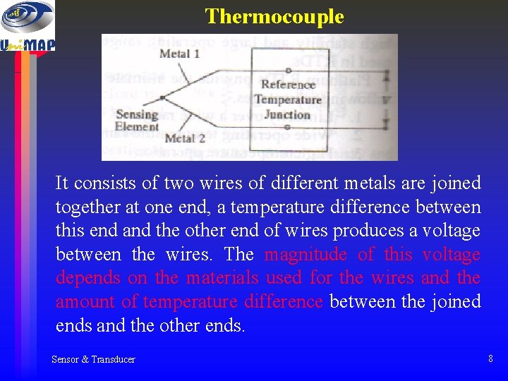
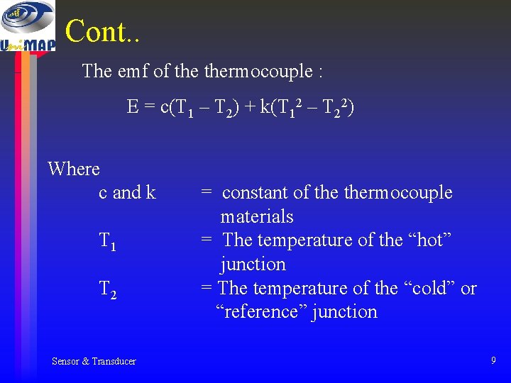
Thermocouple It consists of two wires of different metals are joined together at one end, a temperature difference between this end and the other end of wires produces a voltage between the wires. The magnitude of this voltage depends on the materials used for the wires and the amount of temperature difference between the joined ends and the other ends. Sensor & Transducer 8
Cont. . The emf of thermocouple : E = c(T 1 – T 2) + k(T 12 – T 22) Where c and k T 1 T 2 Sensor & Transducer = constant of thermocouple materials = The temperature of the “hot” junction = The temperature of the “cold” or “reference” junction 9
Thermistor A thermistor is a semiconductor made by sintering mixtures of metallic oxide, such as oxides of manganese, nickel, cobalt, copper and uranium. Termistors have negative temperature coefficient. That is, their resistance decreases as their temperature rises. Types of thermistor Disc Washer Rod Sensor & Transducer Resistance 1 to 1 MΩ 1 to 50 kΩ high resistance 10
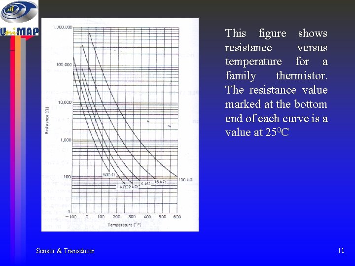
This figure shows resistance versus temperature for a family thermistor. The resistance value marked at the bottom end of each curve is a value at 250 C Sensor & Transducer 11
Advantages of thermistor • Small size and low cost • Fast response over narrow temperature range • Good sensitivity in Negative Temperature Coefficient (NTC) region • Cold junction compensation not required due to dependence of resistance on absolute temperature. • Contact and lead resistance problems not encountered due to large resistance Sensor & Transducer 12
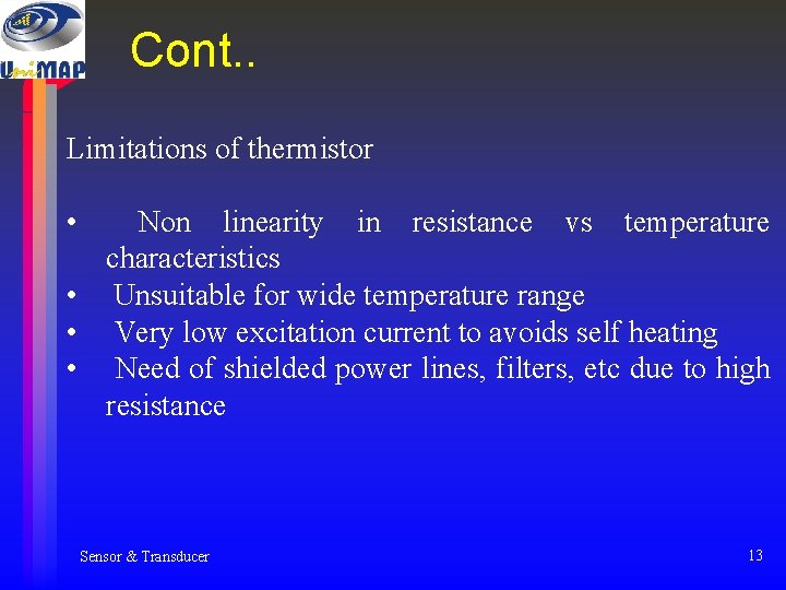
Cont. . Limitations of thermistor • Non linearity in resistance vs temperature characteristics • Unsuitable for wide temperature range • Very low excitation current to avoids self heating • Need of shielded power lines, filters, etc due to high resistance Sensor & Transducer 13
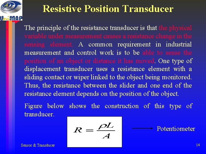
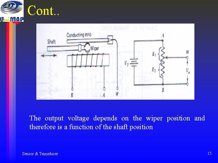
Resistive Position Transducer The principle of the resistance transducer is that the physical variable under measurement causes a resistance change in the sensing element. A common requirement in industrial measurement and control work is to be able to sense the position of an object or distance it has moved. One type of displacement transducer uses a resistance element with a sliding contact or wiper linked to the object being monitored. Thus, the resistance between the slider and one end of the resistance element depends on the position of the object. Figure below shows the construction of this type of transducer. Potentiometer Sensor & Transducer 14
Cont. . The output voltage depends on the wiper position and therefore is a function of the shaft position Sensor & Transducer 15
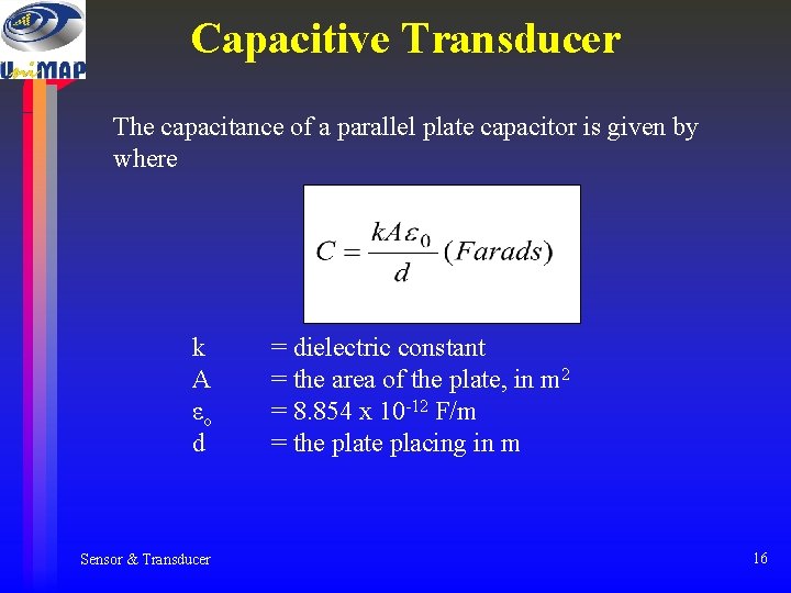
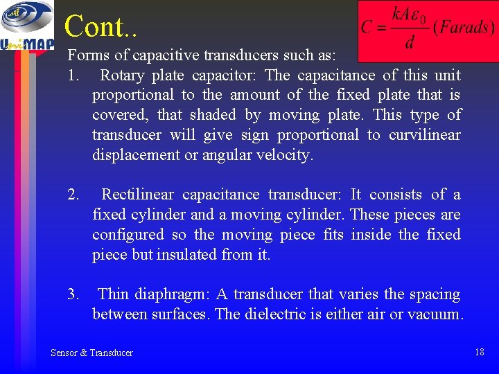
Capacitive Transducer The capacitance of a parallel plate capacitor is given by where k A εo d Sensor & Transducer = dielectric constant = the area of the plate, in m 2 = 8. 854 x 10 -12 F/m = the plate placing in m 16
Cont. . Sensor & Transducer 17
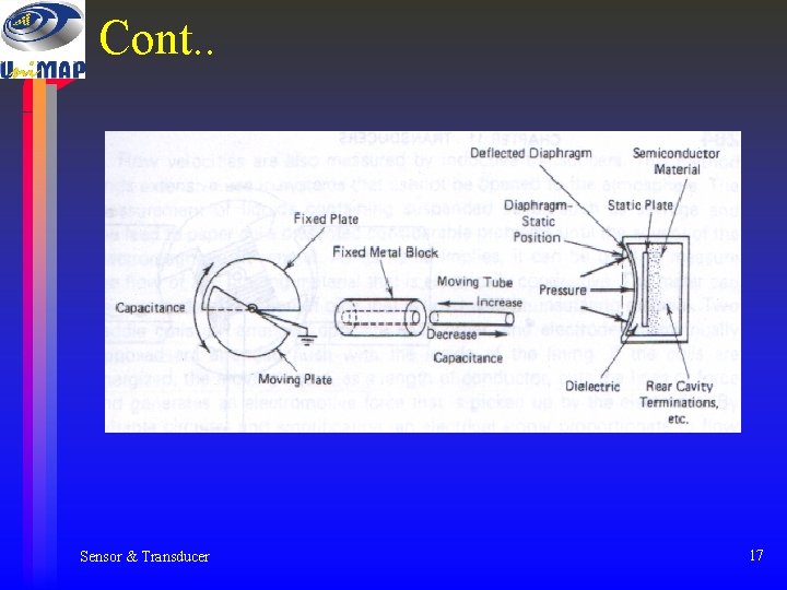
Cont. . Forms of capacitive transducers such as: 1. Rotary plate capacitor: The capacitance of this unit proportional to the amount of the fixed plate that is covered, that shaded by moving plate. This type of transducer will give sign proportional to curvilinear displacement or angular velocity. 2. Rectilinear capacitance transducer: It consists of a fixed cylinder and a moving cylinder. These pieces are configured so the moving piece fits inside the fixed piece but insulated from it. 3. Thin diaphragm: A transducer that varies the spacing between surfaces. The dielectric is either air or vacuum. Sensor & Transducer 18
Cont. . Advantages: 1. Has excellent frequency response 2. Can measure both static and dynamic phenomena. Disadvantages: 1. Sensitivity to temperature variations 2. the possibility of erratic or distortion signals owing to long lead length Applications: 1. As frequency modulator in RF oscillator 2. In capacitance microphone 3. Use the capacitance transducer in an ac bridge circuit Sensor & Transducer 19
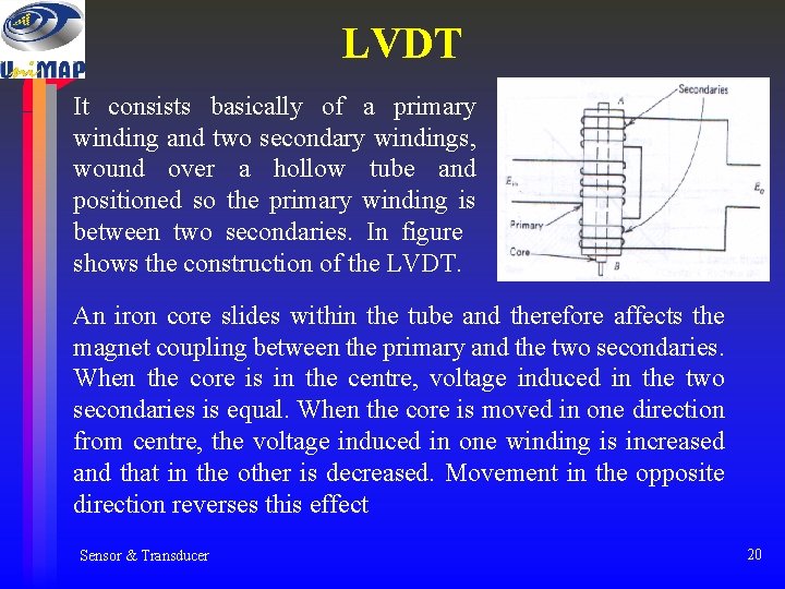
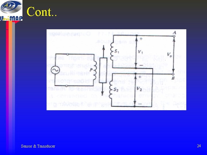
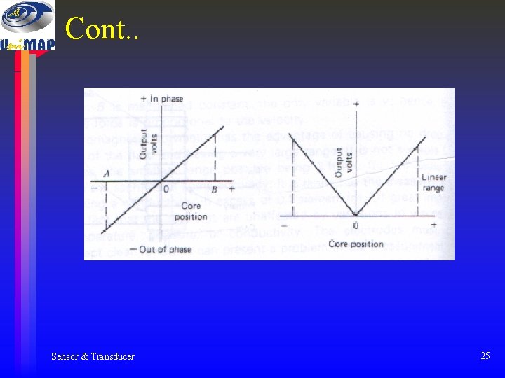
LVDT It consists basically of a primary winding and two secondary windings, wound over a hollow tube and positioned so the primary winding is between two secondaries. In figure shows the construction of the LVDT. An iron core slides within the tube and therefore affects the magnet coupling between the primary and the two secondaries. When the core is in the centre, voltage induced in the two secondaries is equal. When the core is moved in one direction from centre, the voltage induced in one winding is increased and that in the other is decreased. Movement in the opposite direction reverses this effect Sensor & Transducer 20
Inductive Transducer Inductive transducers may be either of the self generating or passive type. The self generating type utilises the basic electrical generator principle, i. e, a motion between a conductor and magnetic field induces a voltage in the conductor (generator action). This relative motion between the field and the conductor is supplied by changes in the measurand. An inductive electromechanical transducer is a device that converts physical motion (position change) into a change in inductance. Transducers of variable inductance type work upon one of the following principles: 1. Variation of self inductance 2. Variation of mutual inductance Sensor & Transducer 21
Cont. . Inductive transducers are mainly used for the measurement of displacement. The displacement to be measured is arranged to cause variation in any of three variables: 1. Number of turns 2. Geometric configuration 3. Permeability of the magnetic material or magnetic circuits Sensor & Transducer 22
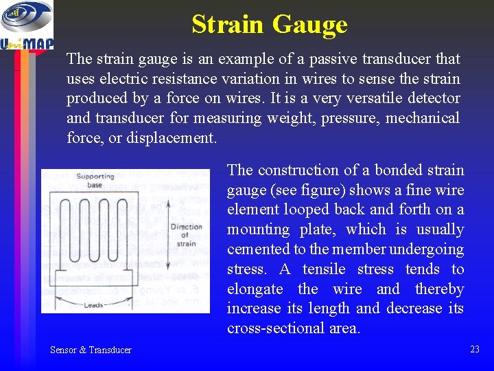
Strain Gauge The strain gauge is an example of a passive transducer that uses electric resistance variation in wires to sense the strain produced by a force on wires. It is a very versatile detector and transducer for measuring weight, pressure, mechanical force, or displacement. The construction of a bonded strain gauge (see figure) shows a fine wire element looped back and forth on a mounting plate, which is usually cemented to the member undergoing stress. A tensile stress tends to elongate the wire and thereby increase its length and decrease its cross-sectional area. Sensor & Transducer 23
Cont. . Sensor & Transducer 24
Cont. . Sensor & Transducer 25
Finish…… Good Luck 4 final! Sensor & Transducer 26