TRANSDUCER Master Copy for IRTMTCALD by IRICEN TRANSDUCER

TRANSDUCER Master Copy for IRTMTC/ALD by IRICEN

TRANSDUCER • Transducer is a device which converts one form of energy to another form • Transducer is a device which converts mechanical energy into electrical energy. §In Track Machines Transducers are used to convert track parameters (Cross Level, Long. level, versine) and Mechanical linear displacement (Tamping Unit, Satellites, Hook etc. ) to electrical signal.

TYPES OF TRANSDUCER v. On the basis of Component Used üVariable Resistance Type § Variable Capacitance Type § Variable Inductance Type v On the basis of Supply Used: üPassive Transducer ---Which need supply § Active Transducer—Which don’t need supply v. On the basis of Signal: üAnalog Transducer § Digital Transducer (In latest machines being used)

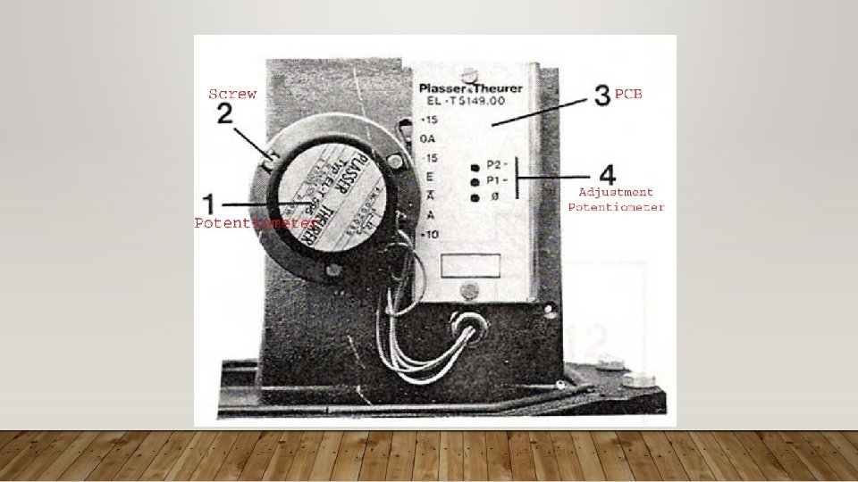
TRANSDUCERS USED IN TRACK MACHINES • In machines transducers are potentiometer type which is basically a variable resistance which shaft is rotated by mechanical arrangement and it generates electrical signal as per deflection. -10 V +10 v 5 KΩ Potentiometer Output

TRANSDUCER Big Gear Attached with Potentiometer Small Gear Attached with Pulley Electrical wire Red (+10 V) Blue (-10 V) Yellow (output)

LINING TRANSDUCER • This transducer converts H 1 versine to electrical signal @ 23. 1 mv/mm. • Output is –ve for right side deflection & +ve for left side deflection. • This transducer is mounted on Lining trolley. • Multicheck address of this transducer is F 01.

LINING TRANSDUCER MOUNTED ON LINING TROLLEY

MEASURING TRANSDUCER • This transducer converts H 2 versine to electrical signal @ 23. 1 mv/mm. • Output is +ve for right side and -ve for leftside. • This transducer is mounted on Measuring trolley. • Multicheck address transducer is F 02. of this

MEASURING TRANSDUCER MOUNTED ON MEASURING TROLLEY

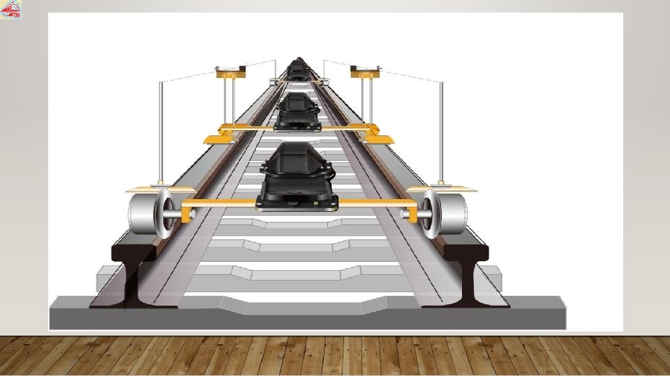
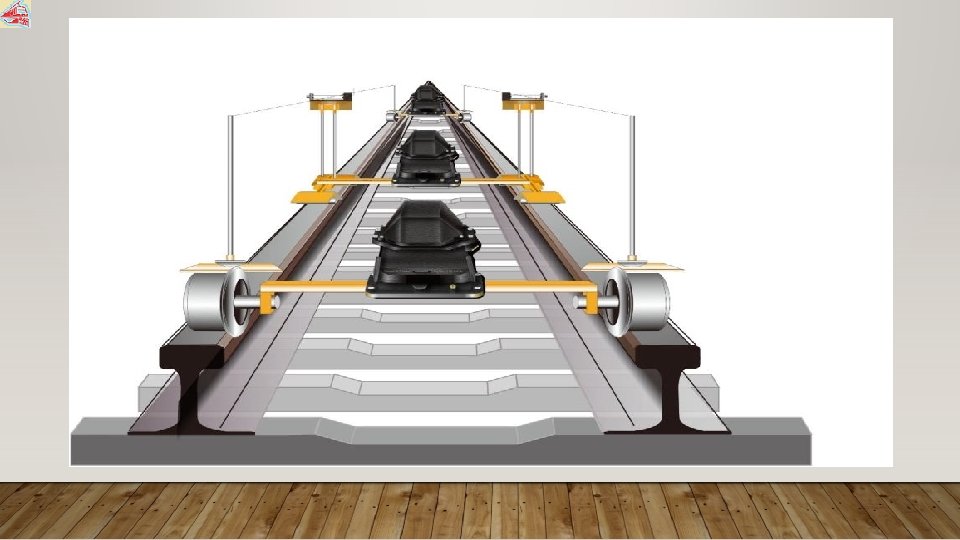
LINING & MEASURING TRANSDUCER MOUNTED ON TROLLEYS • Rear Bogie Measuring Transducer Measuring Bogie Lining Transducer Front Bogie

LINING & MEASURING TRANSDUCER MOUNTED ON TROLLEY

CALIBRATION OF LINING & MEASURING TRANSDUCER For calibration of lining transducer fix the fork of lining transducer at zero lock position, select multicheck address F 01 in multicheck PCB then display of multicheck should show 0 v, if it is not showing zero volt then loose three screws of potentiometer and turn it to get zero volt. After adjustment tight the screws of potentiometer. Before calibration of transducer voltage of potentiometer should be checked. It should be +10 V and – 10 V. If there is any variation, then adjust +10 v and – 10 v in EK 813 SV of lining circuit. Calibration procedure of measuring transducer is same as lining transducer but for calibration of measuring transducer, 4 -pt lining and multicheck address F 02 should be selected.

PENDULUM • Pendulum converts cross level error to electrical signal at the rate of 25 mv/mm. • If left rail is high then it’s output is – ve, if right rail is high then it’s output is +ve. • There are three pendulums in CSM & 09 -3 X and DGS , two in other tamping machines.


FUNCTION OF PENDULUM Front Pendulum: • For automatic cross level correction or to maintain fed SE. Middle Pendulum: • For indication only. Rear Pendulum: • For twist correction, recording purpose.

REAR PENDULUM

MIDDLE PENDULUM

FRONT PENDULUM

CALIBRATION OF PENDULUM Mechanical Adjustment: Lower the pendulam trolley on track where cross level is zero, check the spirit level of pendulum it should be on zero. If it is not in zero position then adjust check nut of pendulum to bring spirit level in zero position. Electrical Zero Adjustment: Select Multicheck address of pendulam, selector switch should be on 2 nd position. Display should show zero volt , if it is not zero volt then adjust potentiometer P 3 in pendulum PCB to get zero volt on display. Right Side Cant Adjustment: Place 100 mm shim under RH side feeler rod/wheel of trolley and check output of pendulum on display. It should be +2. 5 V, if it is not +2. 5 V then adjust potentiometer P 1 in pendulum PCB to get +2. 5 V. After adjustment remove shim. Left Side Cant Adjustment: Place 100 mm shim under LH feeler rod /wheel of pendulam trolley and check output of pendulum on display. It should be – 2. 5 V, if it is not – 2. 5 V then adjust potentiometer P 2 in pendulum PCB to get – 2. 5 V.

HEIGHT TRANSDUCER • This transducer converts longitudinal level to electrical signal @ 90 mv/mm. • There are two height transducers used in tamping machines. • Multi-check address of transducer is F 0 D(Left) F 0 E(Right). this and

HEIGHT TRANSDUCER

LEVELLING PRINCIPLE • Longitudinal level of track is corrected by Proportional LEVELLING WORKING DIRECTION c b a R R=REAR MEASURING POINT M=MEASURING AND CORRECTION POINT F= FRONT MEASURING TOWER M F

CALIBRATION OF HEIGHT TRANSDUCER: • For calibration of Height Transducers 30 m to 40 m track should be longitudinal & cross level error free and provide shim if necessary to get zero longitudinal level track under all three feeler rods (Front, middle and rear) • Mechanical Adjustment : • Lower all three trolleys on zero level track • Apply levelling chord tension. • Arm of height transducer should be parallel to track if not then adjust checknut up or down as required to bring arm parallel to track.

CALIBRATION OF HEIGHT TRANSDUCER: • Electrical Calibration: • Switch on lifting circuit. • Keep all input potentiometers • (General lift, Cant and Cross level correction potentiometer etc. ) at zero. • Select multicheck address of height transducers F 0 D or F 0 E • Arm of height transducer should be parallel to track in horizontal and output signal should be 0 V, pointer of lift indicator should be in center position. • If electrical signal is not zero then adjust potentiometer of height transducer by loosing screw. Zero Signal should be checked on F 0 D for Left height transducer and on F 0 E for Right height transducer. After adjustment , tight the screws of potentiometer and fit the cover

HEIGHT TRANSDUCER

HEIGHT TRANSDUCER RHS HT LHS HT

TAMPING DEPTH TRANSDUCERELT-1330 • This transducer converts displacement of tamping unit to electrical signal at the rate of 19 mv/mm. • If tamping unit is above center mark It’s output is –ve , if it is below center mark then output is +ve. • It’s multicheck address is F 14 for left & F 15 for right.

TAMPING DEPTRH TRANSDUCER ELT-750 • This transducer converts displacement of tamping unit to electrical signal at the rate of 23 mv/mm. • If tamping unit is above center mark It’s output is –ve , if it is below center mark then output is +ve. • It’s multicheck address is F 14 for left & F 15 for right.

CALIBRATION OF TAMPING DEPTH TRANSDUCER ELT-750 • For calibration of this transducer Multi check address F 14(left) or F 15(Right) should be selected , Tamping unit should be in lock position , T. U. circuit should be on. • In this position output voltage of transducer should be -7. 5 V. • if -7. 5 V is not there, then loose three screws of potentiometer , turn it to get required voltage. after adjustment tight the screws and fit the cover.

CALIBRATION OF PORTABLE TAMPING DEPTRH TRANSDUCER IN CSM-3 X/NEW WST/MPT • In CSM-3 X/New WST/MPT output voltage of transducer in lock condition should be – 4. 5 Volt, if it is not loose three screws of potentiometer , turn it to get required voltage. after adjustment tight the screws and fit the cover

HOOK TRANSDUCER • This transducer converts displacement of hook to electrical signal at the rate of 23 mv/mm. • If hook is above then its output is –ve, +ve if hook is below. • Its multicheck address is F 18(Left) and F 19(Right). • Calibration: - For calibration of hook transducer hook should be in up position , in this position output voltage of hook transducer should be -2. 1 Volt. If output is not -2. 1 V then loose three screws of potentiometer and adjust it to get -2. 1 V.

SATELLITE TRANSDUCER IN CSM • This Transducer converts displacement of satellite to electrical signal @11 mv/mm. Satellite Transducer is provided only in CSM & 09 -3 X. • Calibration For calibration of Satellite Transducer, lock the satellite unit in front zero position, measure output voltage of transducer , it should be +8. 2 V. If it is not +8. 2 v, then open the cover of transducer and loose three screws of potentiometer and adjust it to get +8. 2 V. After adjustment tight the screws and fit the cover of transducer and release the satellite from front zero position.

SATELLITE TRANSDUCER IN 09 -3 X • This Transducer converts displacement of satellite to electrical signal @ 8 mv/mm. Satellite Transducer is provided only in CSM & 09 -3 X. • Calibration For calibration of satellite transducer in 09 -3 X Satellite should be locked in rear position , in this position output voltage of transducer should be -8. 6 V. If it is not then open the cover of transducer and loose the screw of potentiometer and adjust potentiometer to get -8. 6 V.

ENCODER • This is a digital transducer which converts displacement of machine to digital signal at the rate of 1000 Pulse/meter. This is mounted on front trolley. This transducer is used in CSM, 09 -3 X, DGS and machines with ALC
- Slides: 37