Positron Sources for future colliders q Positron sources
")


")


![Positron requirements / beam parameters Parameter Unit [] ILC CLIC SLC FCC-ee Lemma-scheme Bunch](https://slidetodoc.com/presentation_image_h2/caff7a6a5f7941fef4e7e368cdf88e6a/image-14.jpg "Positron requirements / beam parameters Parameter Unit [] ILC CLIC SLC FCC-ee Lemma-scheme Bunch")


- Slides: 19
Positron Sources for future colliders q Positron sources for Linear Colliders (CLIC and ILC) and for the circular collider FCC-ee q Comparison of requirements and performances q Lemma scheme q Comments and conclusions Steffen Doebert, BE-RF Muon Collider Workshop, CERN 9 -11 October 2019
ILC positron source ~ 30% positron polarization Undulator driven with 125 Ge. V electrons produces gamma’s for positron production
ILC positron source, alternative
ILC positron source, target area Meter’s of shielding and a sophisticated target exchange concept Positron sources need space
CLIC complex, 3 Te. V
The CLIC Injector Complex > 1 km • Pre-damping ring can be avoided if the beam emittance is ~ < 25 mm (norm) • Positron emittance before pre-damping ring: 7 mm • Main damping ring; in: exn/eyn = 65/10 mm out: exn/eyn = 472/5 nm • Bunch compressors needed after the rings for further acceleration
CLIC Positron Source q q q Generation of adequate photons (0 -20 Me. V) for pair production Complex and lossy positron collection and capture system Performance limited often by peak energy deposit density (PEDD < 35 J/g pulse) Very high radiation area, constraints for operation and maintenance, engineering challenge Long solenoidal field for guidance
Previous studies: The Pre-Injector Linac The total yield: 8. 0 e+/e- Aperture 20 mm ! 2. 8 e+/e- 1. 09 e+/e 0. 98 e+/e- (effective) e+ Target AMD Solenoid TW Structures The effective yield : (-20, 20) degrees in phase and (150, 250) Me. V in energy Total yield: 0. 89 e+/e. Effective yield: 0. 50 e+/e- Parameters of the accelerating structures in the Pre-Injector linac Parameters Unit Value Cell length cm 5 Frequency GHz 2 Phase advance per cell π 2/3 Average axial electric field MV/m 15 Acceleration Total yield: 0. 93 e+/e. Effective yield: 0. 48 e+/e- Deceleration C. Bayar
Injector Linac • All positrons are within 1% acceptance window of the pre-damping ring. The effective yield : (-20, 20) degrees in phase and (150, 250) Me. V in energy Energy (Ge. V) 5 (new) 5 (previous) 5 (CDR) Target exit (e+/e-) 7. 14 8. 00 AMD exit (e+/e-) 3. 06 2. 80 2. 10 Total yield (e+/e-) 1. 36 1. 09 0. 95 Effective yield (e+/e-) 1. 21 0. 98 0. 38 C. Bayar
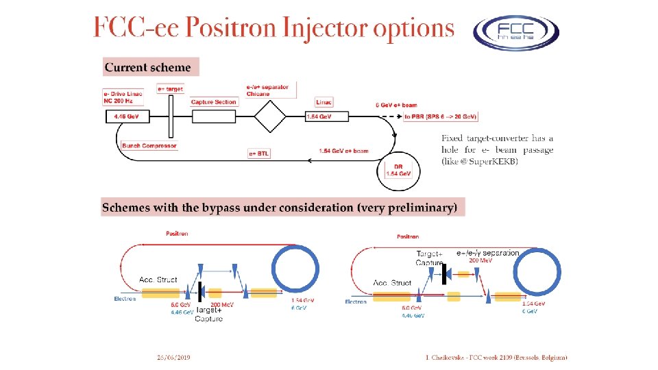
FCC-ee positron source Collider rings 16640 bunches 1. 7 x 10¹¹ / bunch ✤ ✤ injection scheme for Z Main Booster Ring (BR) 16640 bunches, 400 MHz RF Bunches are paired in the linac, with 52. 5 ns separation, assuming a usual SLED. In the common section of e+e- (1. 54 to 6 Ge. V), 1 e- pair for positron production and 1 e+ pair are accelerated by an RF pulse of the Linac in the e+ mode. lse - / pu e f o 1 pair z @ 6 Ge. V 200 H ch or Bunre ss comp e- RF Gun K. Oide of e 1 pair + / pulse ir of e V + 1 pa z @ 6 Ge H 0 20 lse - / pu e r o of e+ e. V 1 pair Hz @ 6 G 200 Pre-Booster Ring (PBR) ∼ 1190 bunches, 400 MHz RF Fluxtrator n conce ) g (DR g Rin es n i p m h e+ Da rs of bunc i 8 pa ✤ ✤ Bunch charge does not change from the linac through BR. It is accumulated only in the collider. PBR needs 14 cycles to fill BR, due to the ratio of the circumferences (M. Benedikt).
The Lemma 0 scheme 3 new positrons reinjected to replace the lost ones Cuts: 5 -20 Me. V R= 0. 5 cm R’=0. 5 rad Yields about 10 From F. Collamati at Posipol 2018
The Lemma 1 scheme Not many details about the positron recovery schemes yet !
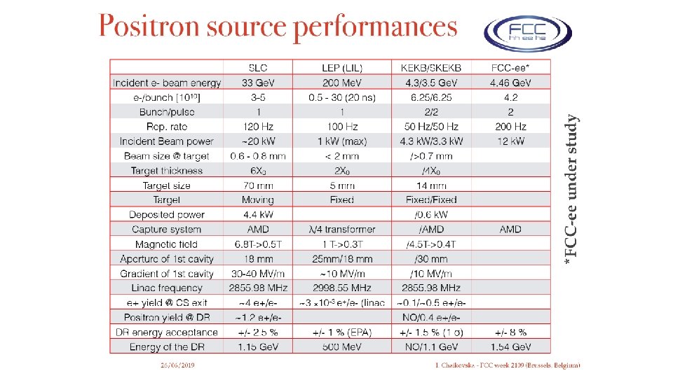
Positron requirements / beam parameters Parameter Unit [] ILC CLIC SLC FCC-ee Lemma-scheme Bunch charge N [109] 20 -30 6 3 -5 21 / 170 315 Emittance norm ex/ey [nm] 104/35 660/20 104/90 5 104 Bunches per train n 1312 352 1 2 100 Repetition rate [Hz] 5 50 120 200 5 MHz/100 k. Hz Particles /s N [1014]/[s] 1. 3 0. 58 0. 06 0. 0852 1018 / 1016 Positron yield e+/e- 8 /1. 28 8/ 1. 3 ~20 /1. 25 11/0. 7 80 e+/e+ Collection efficiency e+/e+ (%) 16 16 ~ few % 6 17 % ? PEDD J/g 33. 6 18 35 17 Beam power on target / photons [k. W] 48 / 60 64 20 12 MW ? Deposited power [k. W] 12 11 4. 4 2. 1 MW ? Careful, numbers might be not all consistent !
Positron Challenges within the Lemma scheme some comments q Full positron source with linear collider intensities needed to fill the ring with numerous injections q Without recovery two orders of magnitude higher positron flux then linear colliders, four orders of magnitude compared to tested systems recovery needed, still 1016 e+/s q Intensity of photon beam very high, MW on target, existing sources in k. W range, neutron source type beam power (ESS: 5 MW), if possible likely not small q Power scaling: Order of 100 MW positron beam power compared to 28 MW in 3 Te. V CLIC
Positron Challenges within the Lemma scheme q Innovative but challenging system for recovery to compensate positron loss per turn, collection efficiency to be determined, not clear how the studied cuts compare to full capture system simulations Likely on the optimistic side q Recovered positrons arrive at the bunch distance of the ring (5 MHz cw for example), sc cw linac ? q Top up injection at 45 Ge. V ? , Emittance ? q Is a damping ring for the positrons needed, timing scheme implications q Huge integration problem in case of recovery, size of the target systems, very close to the ring and the Muon target
Conclusions q Positron sources are by no means trivial q Already very challenging for conventional linear colliders, may be considered as state of the art q Lemma scheme parameters are clearly beyond the state of the art. Major R&D effort needed to get confidence in feasibility q Without extremely stable and reliable source no luminosity !!!
Typical requirements for a Positron Source for a collider for high energy physics q Delivers required intensity ~ 109 -1010 per bunch q Requires typically a yield of ~ > 1 if produced with primary electron beam q Extremely reliable and stable because the “complicated part” comes afterwards q Small energy spread before injection into damping ring DE/E ~ 1% q Extremely small emittance, needed for luminosity goals; implies flat beams Requires in general one or two damping rings ! q Synchronised with electron beam q Polarized beams preferred by physics q Low cost compared to collider total ( in reality a significant fraction) q Polarised electron beam (~80%) is “standard” for linear colliders