Physics 2102 Jonathan Dowling James Clerk Maxwell 1831
 Lecture 34: MON 13 APR")


 waves (light) are visible is")
 Wave, Qualitatively An LC oscillator causes currents to flow sinusoidally,")


- Slides: 23
Physics 2102 Jonathan Dowling James Clerk Maxwell (1831 -1879) Lecture 34: MON 13 APR Ch. 33. 1– 3, 5– 7: E&M Waves
MT 03 Avg: 65/100 Q 1/P 3 K. Schafer Office hours: MW 1: 30 -2: 30 pm 222 B Nicholson P 1/Q 2 J. Dowling Office hours: MWF 10: 30 -11: 30 am 453 Nicholson P 2/Q 3 M. Gaarde Office hours: TTh 2: 30 -3: 30 pm 215 B Nicholson P 3/Q 2 C. Buth Office hours: MF 2: 30 -3: 30 pm 222 A Nicholson A: 90 -100 B: 80 -89 C: 60 -79 D: 50 -59
Right Hand Rule & Vector Addition! Right Hand Rule & BI>BII Since I is Closer!
Maxwell, Waves and Light A solution to the Maxwell equations in empty space is a “traveling wave”… electric and magnetic “forces” can travel! The “electric” waves travel at the speed of light! Light itself is a wave of electricity and magnetism!
Electromagnetic Waves A solution to Maxwell’s equations in free space: Visible light, infrared, ultraviolet, radio waves, X rays, Gamma rays are all electromagnetic waves.
Radio waves are reflected by the layer of the Earth’s atmosphere called the ionosphere. This allows for transmission between two points which are far from each other on the globe, despite the curvature of the earth. Marconi’s experiment discovered the ionosphere! Experts thought he was crazy and this would never work.
Maxwell’s Rainbow The wavelength/frequency range in which electromagnetic (EM) waves (light) are visible is only a tiny fraction of the entire electromagnetic spectrum. Fig. 33 -2 Fig. 33 -1 (33 -2)
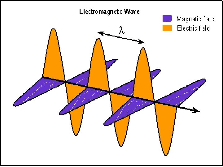
The Traveling Electromagnetic (EM) Wave, Qualitatively An LC oscillator causes currents to flow sinusoidally, which in turn produces oscillating electric and magnetic fields, which then propagate through space as EM waves. Next slide Fig. 33 -3 Oscillation Frequency: (33 -3)
Mathematical Description of Traveling EM Waves Electric Field: Wave Speed: Magnetic Field: All EM waves travel a c in vacuum Wavenumber: EM Wave Simulation Frequency: Vacuum Permittivity: Vacuum Permeability: Fig. 33 -5 Amplitude Ratio: Magnitude Ratio: (33 -5)
The Poynting Vector: Points in Direction of Power Flow Electromagnetic waves are able to transport energy from transmitter to receiver (example: from the Sun to our skin). The power transported by the wave and its direction is quantified by the Poynting vector. John Henry Poynting (1852 -1914) For a wave, since E is perpendicular to B: In a wave, the fields change with time. Therefore the Poynting vector changes too!! Units: Watt/m 2 E S B The direction is constant, but the magnitude changes from 0 to a maximum value.
EM Wave Intensity, Energy Density A better measure of the amount of energy in an EM wave is obtained by averaging the Poynting vector over one wave cycle. The resulting quantity is called intensity. Units are also Watts/m 2. The average of sin 2 over one cycle is ½: or, Both fields have the same energy density. The total EM energy density is then
Solar Energy The light from the sun has an intensity of about 1 k. W/m 2. What would be the total power incident on a roof of dimensions 8 m x 20 m ? I = 1 k. W/m 2 is power per unit area. P = IA = (103 W/m 2) x 8 m x 20 m = 0. 16 Mega. Watt! ! The solar panel shown (BP 275) has dimensions 47 in x 29 in. The incident power is then 880 W. The actual solar panel delivers 75 W (4. 45 A at 17 V): less than 10% efficiency…. The electric meter on a solar home runs backwards — Entergy Pays YOU!
EM Spherical Waves The intensity of a wave is power per unit area. If one has a source that emits isotropically (equally in all directions) the power emitted by the source pierces a larger and larger sphere as the wave travels outwards: 1/r 2 Law! So the power per unit area decreases as the inverse of distance squared.
Example A radio station transmits a 10 k. W signal at a frequency of 100 MHz. At a distance of 1 km from the antenna, find the amplitude of the electric and magnetic field strengths, and the energy incident normally on a square plate of side 10 cm in 5 minutes. Received energy:
Radiation Pressure Waves not only carry energy but also momentum. The effect is very small (we don’t ordinarily feel pressure from light). If light is completely absorbed during an interval Dt, the momentum transferred is given by and twice as much if reflected. F A Newton’s law: Now, supposing one has a wave that hits a surface of area A (perpendicularly), the amount of energy transferred to that surface in time Dt will be I therefore Radiation pressure: [N/m 2]
Radiation Pressure & Comet Tails
Solar Sails: Photons Propel Spacecraft! Star. Trek DS 9 NASA Demo NASA Concept
EM waves: polarization Radio transmitter: If the dipole antenna is vertical, so will be the electric fields. The magnetic field will be horizontal. The radio wave generated is said to be “polarized”. In general light sources produce “unpolarized waves”emitted by atomic motions in random directions.
EM Waves: Polarization Completely unpolarized light will have equal components in horizontal and vertical directions. Therefore running the light through a polarizer will cut the intensity in half: I=I 0/2 When polarized light hits a polarizing sheet, only the component of the field aligned with the sheet will get through. And therefore:
Example Initially unpolarized light of intensity I 0 is sent into a system of three polarizers as shown. What fraction of the initial intensity emerges from the system? What is the polarization of the exiting light? • Through the first polarizer: unpolarized to polarized, so I 1=½I 0. • Into the second polarizer, the light is now vertically polarized. Then, I 2 = I 1 cos 260 o = 1/4 I 1 = 1/8 I 0. o • Now the light is again polarized, but at 60. The last polarizer is horizontal, so I 3 = I 2 cos 230 o = 3/4 I 2 =3 /32 I 0 = 0. 094 I 0. • The exiting light is horizontally polarized, and has 9% of the original amplitude.