MICROMECHANICAL RESONATORS Introduction A mechanical resonator is essentially


 it can be seen that if neither the voltage")
 is in the range")
 VP is added")


 σ0, h and Lr are the residual")
- Slides: 19
MICROMECHANICAL RESONATORS
Introduction • A mechanical resonator is essentially a mechanical structure that can be driven into vibration at one or more of its resonance frequencies by one or more appropriately applied forces. • Micromechanical resonators are fundamentally micro-scale versions of their macroscopic counterparts. • However, the difference between micromechanical and macro-scale go beyond mere dimensional quantities.
Resonator Theory and Operation • Micromechanical resonators are key element in the realization of the MEMS filters, mixers and oscillators, • Also they offer the potential for very high Q`s in the context of conventional IC processes; as their Q determines the insertion loss and phase noise respectively.
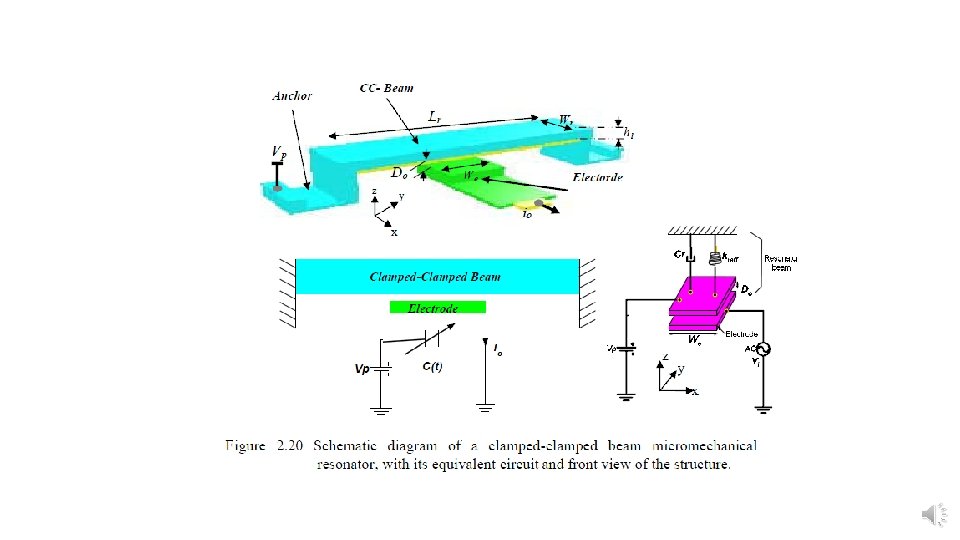
• this work utilizes the simple clamped-clamped beam resonator under a typical bias and excitation configuration. • A simple schematic of a clamped-clamped MEMS resonator is shown in Figure 2. 20.
Clamped-clamped beam resonator operation • The MEMS resonator shown is comprised of three main elements: • excitation electrode, • vibrating mechanical structure, • DC bias supply and current readout. • The vibrating structure in this case is a doubly anchored (also known as “fixed-fixed”) beam suspended a distance Do above an excitation electrode. • Basically, a parallel-plate capacitor is formed between the electrode and the area of the suspended beam directly above the electrode.
• The device is driven into motion electrostatically by the parallel capacitive transducer formed by the resonator beam and the electrode. • Under normal operation, a dc-bias is applied to the resonator, while an ac excitation is applied to the electrodes, which imposes an ac force on the resonator. • When the frequency of the ac input matches the resonance frequency of the structure, the resonator begins to vibrate in a direction perpendicular to the substrate, creating a time-varying capacitor at the transducer. • The dc-bias applied across this time-varying capacitor then generates an output current, which when plotted against input frequency, yields a bandpass biquad transfer function, useful for both filtering and oscillator functions in communications. • For the understanding of the operation of an RF MEMS micromechanical resonator there are important concepts and parameters such as resonance frequency and Q that need to be clear.
Actuation and detection methods • Different resonator actuation and detection methods have been described and used [13, 14, 15]. • The one technique most commonly used for micromechanical resonator is the capacitive (electrostatic actuation and detection). • The change in output current for the electrostatic actuation is caused by the change in charge across the vibrating resonator which behaves as a time varying capacitor. • This technique is described in more detail in the following section.
Electrostatic actuation • When electrostatic force is used, a dc-bias VP is applied to the suspended beam, and an ac input voltage vi = Vm sin ωt (Vm is in the range of the m. V) is applied to the electrode under the beam (see figure 2. 1). • Therefore, the resulting electrostatic potential across the beam is
• In a vibrating resonator, the capacitance formed between the bottom electrode and the beam is changing with time. • Therefore, the charge stored in the capacitor is also changing with time, which implies a current flow. • The expression for the current flowing through a capacitor is:
• From (2. 11) it can be seen that if neither the voltage nor the capacitance varies with time, the current will be zero. Therefore, in steady state, the current for a purely dc input would be zero. • Now, let v=vi. If the frequency of this input signal is far from the natural frequency of the beam ( ), the beam does not vibrate, and therefore the capacitance between the beam and the electrode does not change with time. The second term in (2. 11) becomes zero, and the total current becomes io = C ∂vi/∂t. • As the frequency of the ac signal approaches the natural frequency of the beam, it begins to vibrate, creating a time varying capacitor. Then the current is given by (2. 11) with v = vi. • The third input v = vi + VP results in a current given by (2. 12)
• Since the magnitude of the ac signal (Vm) is in the range of m. V and the dc signal is in the range of Volts, the current is significantly increased when the dc signal is added to an ac signal with frequency close to the natural frequency of the resonator. • Knowing that the change of VP with respect of time is zero (∂VP/∂t = 0), equation (2. 12) can be simplified to:
• Now, in the second term in equation (2. 13) VP is added to vi and since the magnitude of the ac signal is in the m. V range, it can be neglected and we get the following equation: • The derivative of capacitance with respect of time (∂C / ∂t) can be expressed as:
• where the derivative of capacitance with respect to the displacement x can be obtained directly from the plate capacitance formula: • where ε 0 is the permitivity of free space, A is the electrode area, d is the initial electrode gap, and x is the beam displacement (see figure 2. 1). • So, after taking the derivate of the capacitance with respect to displacement x we get;
• For a typical vibrating beam the beam displacement is very small when compared to the gap spacing (x<<d). So, equation (2. 17) can be simplified to: • Substituting equation (2. 18) in equation (2. 15) and the result in equation (2. 14), the following equation is obtained:
• Defining the new variable η to be: • Using this variable η (herein after referred as electromechanical transduction factor) equation (2. 19) can be simplified to: • The first term is recognized as the normal ac-current through the capacitor and the second term is the motional current imot = η*∂x/∂t, due to the time varying capacitance.
• Since the current is proportional to the dc-bias, it is reasonable to think of the dc-bias as a parameter to use for getting a more noticeable peak in the transmission spectrum. • However, when the dc-bias voltage VP is sufficiently large, catastrophic failure of the device ensues, in which the resonator beam is pulled down onto the electrode. • This leads to either destruction of the device due to excessive current passing through the now shorted electrode to resonator path.
• The dc-bias voltage VP at which this event occurs is known as the pullin voltage (VPI). • The pull-in voltage can be estimated to be [20]
• Where • In (2. 23) σ0, h and Lr are the residual stress, thickness and length of the beam respectively, and