JAMES W NILSSON SUSAN A RIEDEL ELECTRIC CIRCUITS


 An ideal low-pass filter (b) An ideal high-pass filter")


- Slides: 33
JAMES W. NILSSON & SUSAN A. RIEDEL ELECTRIC CIRCUITS EIGHTH EDITION
CHAPTER 14 INTRODUCTION TO FREQUENCY SELECTIVE CIRCUITS © 2008 Pearson Education
CONTENTS 14. 1 Some Preliminaries 14. 2 Low-Pass Filters 14. 3 High-Pass Filters 14. 4 Bandpass Filters 14. 5 Bandreject Filters © 2008 Pearson Education
14. 1 Some Preliminaries Input signal Filter Output signal The action of a filter on an input signal results in an output signal © 2008 Pearson Education
14. 1 Some Preliminaries A circuit with voltage input and output © 2008 Pearson Education
14. 1 Some Preliminaries ØA frequency selective circuit, or filter, enables signals at certain frequencies to reach the output, and it attenuates signal at other frequencies to prevent them from reaching the output. Ø The passband contains the frequencies of those signals that are passed; the stopband contains the frequencies of those signals that are attenuated. © 2008 Pearson Education
14. 1 Some Preliminaries (a) An ideal low-pass filter (b) An ideal high-pass filter (c) An ideal bandpass filter (d) An ideal bandreject filter Ideal frequency response plots of the four types of filter circuits © 2008 Pearson Education
14. 2 Low-Pass Filters A series RL low-pass filter. The equivalent circuit at ω = 0. The equivalent circuit at ω = ∞. © 2008 Pearson Education
14. 2 Low-Pass Filters The frequency response plot for the series RL circuit. © 2008 Pearson Education
14. 2 Low-Pass Filters Ø The cutoff frequency, ωc , identifies the location on the frequency axis that separates the stopband from the passband. Ø At the cutoff frequency, the magnitude of the transfer function equals (1 / √ 2) Hmax. © 2008 Pearson Education
14. 2 Low-Pass Filters Cutoff frequency for RL filters © 2008 Pearson Education
14. 2 Low-Pass Filters Example: Designing a Series RC Low-Pass Filter For the series RC circuit in the figure above: a) Find the transfer function between the source voltage and the output voltage. b) Determine an equation for the cutoff frequency in the series RC circuit. c) Choose values for R and C that will yield a low-pass filter with a cutoff frequency of 3 k. Hz. © 2008 Pearson Education
14. 2 Low-Pass Filters ØA low-pass filter passes voltages at frequencies below ωc and attenuates frequencies above ωc. Ø Any circuit with the transfer function Transfer function for a low-pass filter © 2008 Pearson Education
14. 2 Low-Pass Filters Two low-pass filters, the series RL and the series RC, together with their transfer functions and cutoff frequencies © 2008 Pearson Education
14. 3 High-Pass Filters A series RC high-pass filter The equivalent circuit at ω = 0 The equivalent circuit at ω = ∞ © 2008 Pearson Education
14. 3 High-Pass Filters The frequency response plot for the series RC circuit © 2008 Pearson Education
14. 3 High-Pass Filters Example: Designing a Series RL High-Pass Filter. Show that the series RL circuit in the figure below also acts like a high-pass filter: a) Derive an expression for the circuit’s transfer function. b) Use the result from (a) to determine an equation for the cutoff frequency in the series RL circuit. c) Choose values for R and L that will yield a high-pass filter with a cutoff frequency of 15 k. Hz. © 2008 Pearson Education
14. 3 High-Pass Filters ØA high-pass filter passes voltages at frequencies above ωc and attenuates voltages at frequencies below ωc. Any circuit with the transfer function Transfer function for a high-pass filter © 2008 Pearson Education
14. 3 High-Pass Filters Two high-pass filters, the series RC and the series RL, together with their transfer functions and cutoff frequencies © 2008 Pearson Education
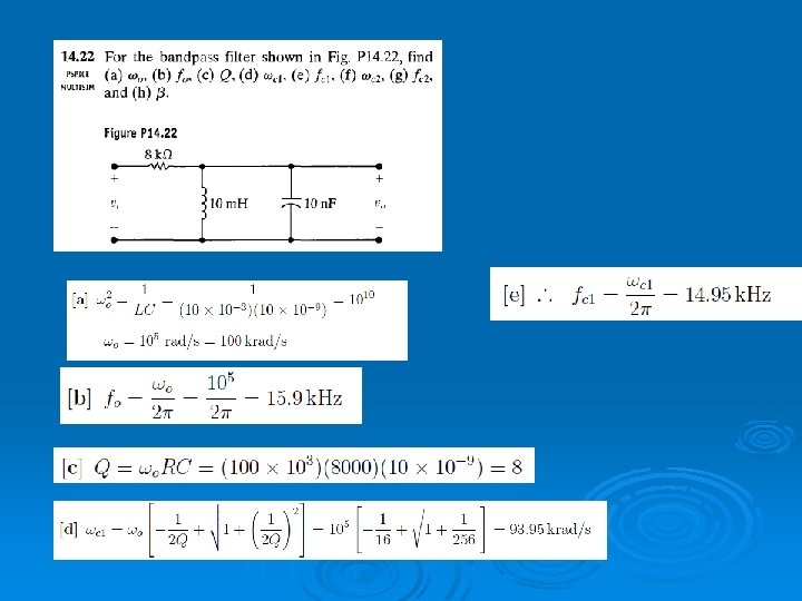
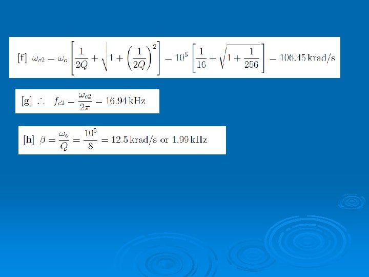
14. 4 Bandpass Filters Ø Bandpass filters and bandreject filters each have two cutoff frequencies, ωc 1 and ωc 2. Ø These filters are further characterized by their center frequency (ω0), bandwidth (β), and quality factor (Q). © 2008 Pearson Education
14. 4 Bandpass Filters Center frequency © 2008 Pearson Education
14. 4 Bandpass Filters Cutoff frequencies, series RLC filters © 2008 Pearson Education
14. 4 Bandpass Filters These quantities are defined as Relationship between center frequency and cutoff frequencies Relationship between bandwidth and cutoff frequencies Quality factor © 2008 Pearson Education
14. 4 Bandpass Filters ØA bandpass filter passes voltages at frequencies within the passband, which is between ωc 1 and ωc 2. Ø It attenuates frequencies outside of the passband. Transfer function for RLC bandpass filter © 2008 Pearson Education
14. 4 Bandpass Filters Two RLC bandpass filters, together with equations for the transfer function, center frequency, and bandwidth of each © 2008 Pearson Education
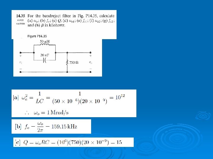
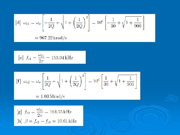
14. 5 Bandreject Filters ØA bandreject filter attenuates voltages at frequencies within the stopband, which is between ωc 1 and ωc 2. Ø It passes frequencies outside of the stopband. © 2008 Pearson Education
14. 5 Bandreject Filters Transfer function for RLC bandreject filter © 2008 Pearson Education
14. 5 Bandreject Filters Two RLC bandreject filters, together with equations for the transfer function, center frequency, and bandwidth of each © 2008 Pearson Education
THE END © 2008 Pearson Education