Indra Nisja STEPPER MOTOR Stepper motors are device


- Slides: 12

Indra Nisja

STEPPER MOTOR Stepper motors are device that rotate by discrete incremental steps The primary advantage: § they can be controlled almost directly by digital circuitry § Although current amplifiers must be placed between the digital control source and the stator windings of a stepper motor, no complex digital-toanalog conversion circuitry is required for controlling motor speed. § They are typically more efficient and develop significantly more torque than the synchronous servomotor. § their ability to operate reliably in an open loop control mode, eliminating the need for complex feedback circuitry.

Three basic (main) types of stepper motors: 1. Permanent magnet (PM) stepper motor 2. Variable reluctance stepper motors 3. Hybrid stepper motors, which is a combination of the previous two. The number of phase windings present in the stator determines the degree by which the motor steps. For the most commonly used industrial stepper motors, this step angle (designated θs) may be as low as 7. 5 o or as high as 30 o. A stepper motor with a small step angle is capable of a higher resolution of motion than a motor with larger step angle. The number of steps required for a given stepper motor to complete one revolution is its stepping rate (designated Rs).

DC Stepping Motor Operation An important principle that applies to the operation of dc stepping motors is the basic law of magnetism: like magnetic poles repel and unlike magnetic poles attract permanent magnet (PM) rotor is placed between two-series connected stator coils, The direction of rotation in this case is unpredictable.

A stepper motor may contain several sets of phase windings. However, for the sake of simplicity, only two pairs are shown here that mounted opposite each other on stator (L 1 -L 3 and L 2 -L 4 pairs). S 1 and S 3 closed S 2 and S 4 closed

Adding two more stator coils to this simple motor, would make the direction of rotation predictable. With the stator polarities indicated, the rotor would align it self midway between the two pairs of stator coils. The direction of rotation can now be predicted and is determined by the polarities of the stator coil sets. Adding more stator coil pairs to a motor of this type improves its rotation and makes the stepping action very accurate.

Since the PM stepper motor shown here has 8 stator windings, the stepping rate is also 8. This is because there are 8 possible positions for the rotor within a single revolution. Thus the stepping angle is determined as:

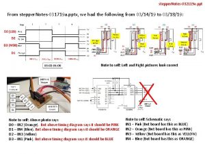
Pulse train required for operation of 4 -phase PM stepper motor

The rotor will require 12 pulses of electricity to move the 12 steps to make one complete revolution. Another way to say this is that the rotor will move precisely 30 o for each pulse of electricity that the motor receives. When no power is applied to the motor, the residual magnetism in the rotor magnet will cause the rotor to detent or align one set of its magnetic poles with the magnetic poles of one of the stator magnets. This means that the rotor will have 12 possible detent positions. Typical stepper motor of the six pole rotor and four pole stator When power is applied, it is directed to only one of the stator pair of windings, which will cause that winding pair to become a magnet. One of the coils for the pair will become the north-pole, and the other will become the south-pole. When this occurs, the stator coil that is the north-pole will attract the closest rotor tooth that has the opposite polarity, and the stator coil that is the south-pole will attract the closest rotor tooth that has the opposite polarity. When current is flowing through these poles, the rotor will now have a much stronger attraction to the stator winding, and the increased torque is called holding torque.

Movement of the stepper motor rotor as current is pulsed to the sataor

Switching Sequence for Full-Step Motors

Half-Step Switching Sequence The main feature of this switching sequence is that we can double the resolution of the stepper motor by causing the rotor to move half the distance it does when the full-step sequence is used

