Finite element analysis of effects of asphalt pavement


- Slides: 16

Finite element analysis of effects of asphalt pavement distresses on FWD dynamic deflection basin Qinglong You Jinglian Ma Xin Qiu Chang’an University

Outline o o o Introduction Objective Development of 3 -D FE Model Parameters of pavement structure and material p Three dimensional finite element model p o Analysis and Results Effect of layer interface between AC and BC layers on deflection p Effect of cracking on deflection p o Conclusions

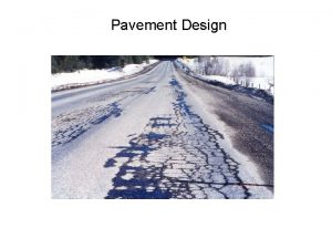
Introduction o o Many asphalt pavements appeared a certain degree of distresses in China FWD is currently used by most highway agencies to determine the structural condition of the highway network

Introduction o The pavement distress such as cracks, the layer interface between an AC layer and a base layer can influence the FWD to evaluate the strength

Objective o o o Development of 3 -D FE Model to simulate the distress on the effect of dynamic deflection basin The effect of interlayer contact between surface course and base course were analyzed The effect of a single transverse cracks, multiple-transverse cracks, longitudinal cracks and block crack on FWD dynamic deflection basin were analyzed.

Development of 3 -D FE Model o Material properties of pavement sections Layer AC BC Sub-BC SG o Thickness (cm) 16 40 15 - Modulus Poisson Density (MPa) ratio (kg·m-3) 3 000 5 000 250 150 0. 35 0. 25 0. 35 0. 40 2 200 2 100 1 900 1 800 Damping ratio 0. 05 The FWD load model number d 1 distance 0 d 2 20 d 3 30 d 4 60 d 5 90 d 6 d 7 120 150 d 8 180 d 9 210

Development of 3 -D FE Model o Build a 3 -D FE pavement model p p 30 m in x-direction, 30 m in the y-direction, and 10 m in the z-direction. Fixed constraint was assigned to the model bottom, while normal displacement constraint was applied to the side areas of the model 3 -D FE Model with Transversal Cracks 3 -D FE Model with a block cracks

Analysis and Results o Effect of layer interface between AC and BC layers on deflection

Analysis and Results o Effect of transverse crack on dynamic deflection basin p Effect of transverse single crack on deflections d=16 cm d=45 cm

Analysis and Results o Effect of transverse crack on dynamic deflection basin p Effect of transverse single crack on deflections d=110 cm d=165 cm

Analysis and Results o Effect of transverse crack on dynamic deflection basin p Effect of transverse multiple cracks on deflections

Analysis and Results o Effect of longitudinal cracks on dynamic deflection basin p Effect of transverse multiple cracks on deflections Loading Position and Dynamic Deflection Basin Crack Gap and Dynamic Deflection Basin

Analysis and Results o Effect of longitudinal cracks on dynamic deflection basin p Block cracks The results indicate that the distribution characteristic has an increasing discrepancy between intact pavements and distressed pavements with increase in crack interval.

Conclusions o The layer interface has a strong influence on deflection points close to the load center p o o When the friction coefficient between the layers is greater than 15, the difference of the last 5 points is no more than 2%. For the transverse multiple crack, the wider the crack width is, the smaller the influence on deflection. When loading point distance from longitudinal cracks is greater than 35 cm, the dynamic deflection is not obvious.

Conclusions (2) o o With the increase in block spacing, there is an increasing difference of the deflection for the first four measurement points. For the transverse single crack, when the distance between the FWD load point and crack is greater than 110 cm, the deflection is the same between the cracked pavement and noncracked pavement. p p Influence of crack width on the deflection is increasing with the increase of the distance from the load center. The impact of different crack width is not obvious.

Thank You Questions ?
 Asphalt pavement design example
 Asphalt pavement design example
 Asphalt pavement thickness design
 Aashto flexible pavement design
 Standard axle load for pavement design
 Alabama asphalt pavement association
 Quiet asphalt pavement
 Flexible pavement
 Difference between rigid and flexible pavement
 Rigid vs flexible pavement
 Truss finite element analysis
 Finite element analysis
 Introduction to finite element analysis and design
 Finite subordinate clauses
 Finite verb
 Learning objectives of non finite verbs
 Finite and non finite clause
