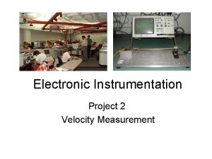
Electronic Instrumentation Project 2 Velocity Measurement ENGR4300 Electronic


- Slides: 30

Electronic Instrumentation Project 2 Velocity Measurement ENGR-4300 Electronic Instrumentation

Cantilever Beam Sensors • Position Measurement – obtained from the strain gauge • Velocity Measurement – obtained from the magnetic pickup coil – not Fall of 2006 • Acceleration Measurement – obtained from the Analog Devices accelerometer 2/20/2021 ENGR-4300 Electronic Instrumentation 2

Sensor Signals • The 2 signals • Position • Acceleration 2/20/2021 ENGR-4300 Electronic Instrumentation 3

Basic Steps for Project • Mount an accelerometer close to the end of the beam • Wire +2. 5 V, -2. 5 V, and signal between IOBoard and Circuit • Record acceleration signal • Reconnect strain gauge circuit • Calibrate the stain gauge • Record position signal • Compare accelerometer and strain gauge signals • Build an integrator circuit to get velocity from the accelerometer sensor • Build a differentiator circuit to get velocity from the strain gauge sensor • Include all calibration and gain constants and compare measurements of velocity 2/20/2021 ENGR-4300 Electronic Instrumentation 4

Building the Accelerometer Circuit 2/20/2021 ENGR-4300 Electronic Instrumentation 5

The Analog Device Accelerometer • The AD Accelerometer is an excellent example of a MEMS device in which a large number of very, very small cantilever beams are used to measure acceleration. A simplified view of a beam is shown here. 2/20/2021 ENGR-4300 Electronic Instrumentation 6

Accelerometer Circuit +2. 5 V -2. 5 V • The AD chip produces a signal proportional to acceleration • +2. 5 V and -2. 5 V supplies are on the IOBoard. • Only 3 wires need to be connected, +2. 5 V, -2. 5 V and the signal. 2/20/2021 ENGR-4300 Electronic Instrumentation 7

Accelerometer Circuit • The ADXL 150 is surface mounted, so we must use a surfboard to connect it to a protoboard 2/20/2021 ENGR-4300 Electronic Instrumentation 8

Caution • Please be very careful with the accelerometers. While they can stand quite large g forces, they are electrically fragile. If you apply the wrong voltages to them, they will be ruined. AD is generous with these devices (you can obtain samples too), but we receive a limited number each year. • Note: this model is obsolete, so you can’t get this one. Others are available. 2/20/2021 ENGR-4300 Electronic Instrumentation 9

Extra Protoboard • You will be given a small protoboard on which you will insert your accelerometer circuit. • Keep your circuit intact until you complete the project. • We have enough accelerometer surfboards that you can keep it until the end of project 2. 2/20/2021 ENGR-4300 Electronic Instrumentation 10

Mounting the Accelerometer 2/20/2021 ENGR-4300 Electronic Instrumentation 11

Mount the Accelerometer Near the End of the Beam • Place the small protoboard as close to the end as practical • The axis of the accelerometer needs to be vertical 2/20/2021 ENGR-4300 Electronic Instrumentation 12

Accelerometer Signal • The output from the accelerometer circuit is 38 m. V per g, where g is the acceleration of gravity. • The equation below includes the units in brackets 2/20/2021 ENGR-4300 Electronic Instrumentation 13

Amplified Strain Gauge Circuit 2/20/2021 ENGR-4300 Electronic Instrumentation 14

Position Measurement Using the Strain Gauge • Set up the amplified strain gauge circuit • Place a ruler near the end of the beam • Make several measurements of bridge output voltage and beam position • Find a simple linear relationship between voltage and beam position (k 1) in V/m. 2/20/2021 ENGR-4300 Electronic Instrumentation 15

Comparing the accelerometer measurements with the strain gauge measurements. • The position, x, is calculated from the strain gauge signal. • The acceleration is calculated from the accelerometer signal. • The two signals can be compared, approximately, by measuring ω. 2/20/2021 ENGR-4300 Electronic Instrumentation 16

Velocity • The velocity is the desired quantity, in this case. • One option – integrate the acceleration signal • Build a Miller integrator circuit - exp. 4 • Need a corner frequency below the beam oscillation frequency • Avoid saturation of the op-amp – gain isn’t too big • Good strong signal – gain isn’t too small • Another option – differentiate the strain gauge signal. • Build an op-amp differentiator – exp. 4 • Corner frequency higher than the beam oscillation frequency • Avoid saturation but keep the signal strong. 2/20/2021 ENGR-4300 Electronic Instrumentation 17

Velocity • One option – integrate the acceleration signal • Build a Miller integrator circuit - exp. 4 • Need a corner frequency below the beam oscillation frequency • Avoid saturation of the op-amp – gain isn’t too big • Good strong signal – gain isn’t too small 2/20/2021 ENGR-4300 Electronic Instrumentation 18

Velocity • Another option – differentiate the strain gauge signal. • Build an op-amp differentiator – exp. 4 • Corner frequency higher than the beam oscillation frequency • Avoid saturation but keep the signal strong. 2/20/2021 ENGR-4300 Electronic Instrumentation 19

Velocity • Be careful to include all gain constants when calculating the velocity. • For the accelerometer • Constant of sensor (. 038 V/g) • Constant for the op-amp integrator (-1/RC) • For the strain gauge • The strain gauge sensitivity constant, k 1 • Constant for the op-amp differentiator (-RC) 2/20/2021 ENGR-4300 Electronic Instrumentation 20

Matlab • Save the data to a file • Open the file with Matlab • faster • Handles 65, 000 points better than Excel • Basic instructions are in the project write up 2/20/2021 ENGR-4300 Electronic Instrumentation 21

Some Questions • How would you use some of the accelerometer signals in your car to enhance your driving experience? • If there are so many accelerometers in present day cars, why is acceleration not displayed for the driver? (If you find a car with one, let us know. ) • If you had a portable accelerometer, what would you do with it? 2/20/2021 ENGR-4300 Electronic Instrumentation 22

Passive Differentiator 2/20/2021 ENGR-4300 Electronic Instrumentation 23

Active Differentiator 2/20/2021 ENGR-4300 Electronic Instrumentation 24

Typical Acceleration • Compare your results with typical acceleration values you can experience. 2/20/2021 Elevator (fast service) 0. 3 g Automobile (take off) 0. 1 -0. 5 g Automobile (brake or corner) 0. 6 -1 g Automobile (racing) 1 -2. 5 g aircraft take off 0. 5 g Earth (free-fall) 1 g Space Shuttle (take off) 3 g parachute landing 3. 5 g Plop down in chair 10 g 30 mph car crash w airbag 60 g football tackle 40 g seat ejection (jet) 100 g jumping flea 200 g high speed car crash 700 g ENGR-4300 Electronic Instrumentation 25

Crash Test Data Ballpark Calc: 56. 6 mph = 25. 3 m/s Stopping in 0. 1 s Acceleration is about -253 m/s 2 = -25. 8 g • Head on crash at 56. 6 mph 2/20/2021 ENGR-4300 Electronic Instrumentation 26

Crash Test Data Ballpark Calc: 112. 1 mph = 50. 1 m/s Stopping in 0. 1 s Acceleration is about -501 m/s 2 = -51. 1 g • Head on crash at 112. 1 mph 2/20/2021 ENGR-4300 Electronic Instrumentation 27

Crash Test Analysis Software • Software can be downloaded from NHTSA website • http: //wwwnrd. nhtsa. dot. gov/software/load-cellanalysis/index. htm 2/20/2021 ENGR-4300 Electronic Instrumentation 28

Crash Videos • http: //www. sph. emory. edu/CIC/CLIPS/m vcrash. html • http: //www. arasvo. com/crown_victoria/c v_movies. htm 2/20/2021 ENGR-4300 Electronic Instrumentation 29

Airbags • Several types of accelerometers are used & at least 2 must sense excessive acceleration to trigger the airbag. 2/20/2021 ENGR-4300 Electronic Instrumentation 30
 Measurement and instrumentation ppt
 Electronic instrumentation rpi
 Rpi electronic instrumentation
 Stepper motor full step sequence
 Darcy's equation
 Angular acceleration and linear acceleration
 Initial velocity and final velocity formula
 Is v final velocity
 What does constant acceleration mean
 Instantaneous velocity vs average velocity
 Darcy velocity vs actual velocity
 Rotational motion and the law of gravity
 Angular acceleration formula in terms of radius
 Streamflow measurement by area velocity method
 Seven core metrics in spm
 Electronic distance measurement
 Scrip exchange
 Electronic news gathering and electronic field production
 Vienna conference on instrumentation
 Piping and instrumentation diagrams
 I/p p&id
 Process control instrumentation technology
 Principles of instrumentation
 Fsr in gas turbine
 Dynamic binary instrumentation
 P&id notation
 Power supply for nim instrumentation
 Near infrared spectroscopy instrumentation
 Man instrument system block diagram
 Layers of protection
 Instrument grasp in dentistry
