Electromyography EMG Instrumentation David Groh University of Nevada









- Slides: 27
Electromyography (EMG) Instrumentation David Groh University of Nevada – Las Vegas
Research Applications of Surface EMG Indicator for muscle activation/deactivation Relationship of force/EMG signal Use of EMG signal as a fatigue index
Types of EMG Electrode Categories n Inserted Fine-wire (Intra-muscular) Needle n Surface
Fine-wire Electrodes Advantages n n Extremely sensitive Record single muscle activity Access to deep musculature Little cross-talk concern Disadvantages n n Extremely sensitive Requires medical personnel, certification Repositioning nearly impossible Detection area may not be representative of entire muscle
Surface Electrodes Advantages n n n Quick, easy to apply No medical supervision, required certification Minimal discomfort Disadvantages n n n Generally used only for superficial muscles Cross-talk concerns No standard electrode placement May affect movement patterns of subject Limitations with recording dynamic muscle activity
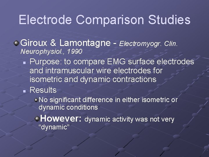
Electrode Comparison Studies Giroux & Lamontagne - Electromyogr. Clin. Neurophysiol. , 1990 n n Purpose: to compare EMG surface electrodes and intramuscular wire electrodes for isometric and dynamic contractions Results No significant difference in either isometric or dynamic conditions However: dynamic activity was not very “dynamic”
EMG Manufacturers Noraxon Motion Lab Systems Delsys
General Concerns Signal-to-noise ratio n Ratio of energy of EMG signal divided by energy of noise signal Distortion of the signal n EMG signal should be altered as minimally as possible for accurate representation
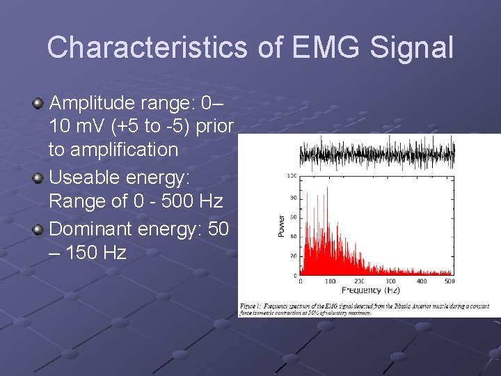
Characteristics of EMG Signal Amplitude range: 0– 10 m. V (+5 to -5) prior to amplification Useable energy: Range of 0 - 500 Hz Dominant energy: 50 – 150 Hz
Characteristics of Electrical Noise Inherent noise in electronics equipment Ambient noise Motion artifact Inherent instability of signal
Inherent Noise in Electronics Equipment Generated by all electronics equipment Frequency range: 0 – several thousand Hz Cannot be eliminated Reduced by using high quality components
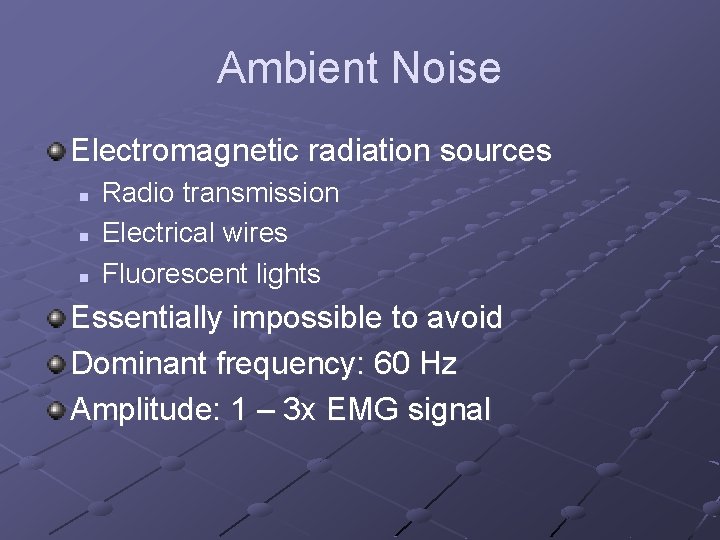
Ambient Noise Electromagnetic radiation sources n n n Radio transmission Electrical wires Fluorescent lights Essentially impossible to avoid Dominant frequency: 60 Hz Amplitude: 1 – 3 x EMG signal
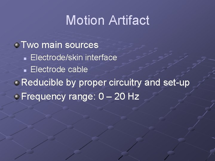
Motion Artifact Two main sources n n Electrode/skin interface Electrode cable Reducible by proper circuitry and set-up Frequency range: 0 – 20 Hz
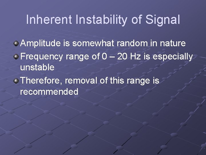
Inherent Instability of Signal Amplitude is somewhat random in nature Frequency range of 0 – 20 Hz is especially unstable Therefore, removal of this range is recommended
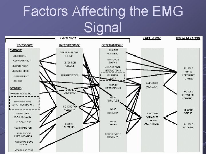
Factors Affecting the EMG Signal Carlo De Luca n Causative Factors – direct affect on signal Extrinsic – electrode structure and placement Intrinsic – physiological, anatomical, biochemical n n Intermediate Factors – physical & physiological phenomena influenced by one or more causative factors Deterministic Factors – influenced by intermediate factors
Factors Affecting the EMG Signal
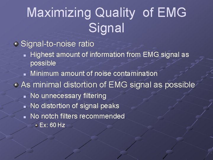
Maximizing Quality of EMG Signal-to-noise ratio n n Highest amount of information from EMG signal as possible Minimum amount of noise contamination As minimal distortion of EMG signal as possible n n n No unnecessary filtering No distortion of signal peaks No notch filters recommended Ex: 60 Hz
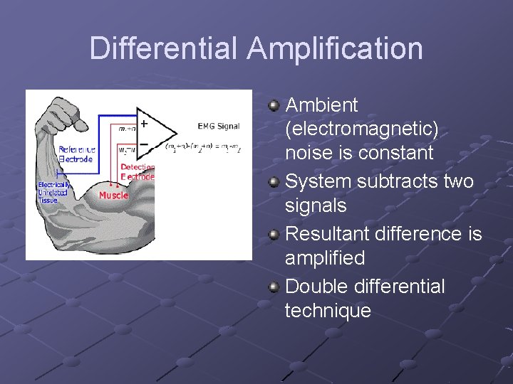
Solutions for Signal Interruption Related to Electrode and Amplifier Design Differential amplification n n Reduces electromagnetic radiation noise Dual electrodes Electrode stability n n Time for chemical reaction to stabilize Important factors: electrode movement, perspiration, humidity changes Improved quality of electrodes n Less need for skin abrasion, hair removal
Differential Amplification Ambient (electromagnetic) noise is constant System subtracts two signals Resultant difference is amplified Double differential technique
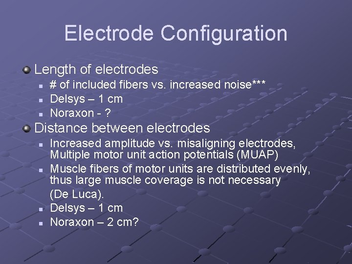
Electrode Configuration Length of electrodes n n n # of included fibers vs. increased noise*** Delsys – 1 cm Noraxon - ? Distance between electrodes n n Increased amplitude vs. misaligning electrodes, Multiple motor unit action potentials (MUAP) Muscle fibers of motor units are distributed evenly, thus large muscle coverage is not necessary (De Luca). Delsys – 1 cm Noraxon – 2 cm?
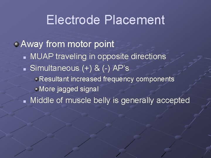
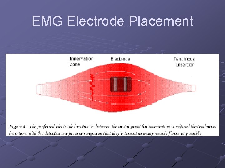
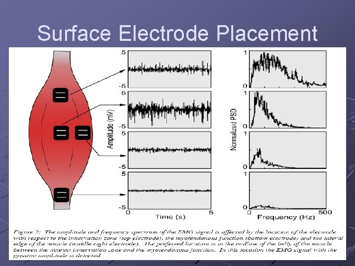
Electrode Placement Away from motor point n n MUAP traveling in opposite directions Simultaneous (+) & (-) AP’s Resultant increased frequency components More jagged signal n Middle of muscle belly is generally accepted
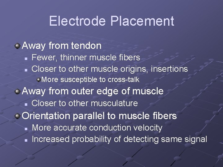
Electrode Placement Away from tendon n n Fewer, thinner muscle fibers Closer to other muscle origins, insertions More susceptible to cross-talk Away from outer edge of muscle n Closer to other musculature Orientation parallel to muscle fibers n n More accurate conduction velocity Increased probability of detecting same signal
EMG Electrode Placement
Surface Electrode Placement
Reference Electrode Placement (Ground) As far away as possible from recording electrodes Electrically neutral tissue n Bony prominence Good electrical contact n n Larger size Good adhesive properties
Off to the Lab!
References Basmajian JV, De Luca CJ. Muscles Alive: their functions revealed by electromyography (fifth ed. ). Williams & Wilkins, Baltimore, Maryland, 1985 Cram JR, Kasman GS. Introduction to surface electromyography. Aspen Publishers, Inc. Gaithersburg, Maryland, 1998 De Luca CJ: Surface electromyography: detection and recording. Del. Sys, Inc. , 2002 De Luca CJ: The use of surface electromyography in biomechanics. J App Biomech 13: 135 -163, 1997 Myo. Research: software for the EMG professional. Scottsdale, Arizona, Noraxon USA, 1996 -1999